Post History
I am using the AD620 as instrumentation amplifier to amplify the body's ECG signal. An ECG is a differential signal (measured with two electrodes) and I want a differential gain of Gd=1000 . The ...
#3: Post edited
by
 Carl
·
2023-03-11T07:55:17Z (about 2 years ago)
Carl
·
2023-03-11T07:55:17Z (about 2 years ago)
- I am using the [AD620 ](https://www.analog.com/media/en/technical-documentation/data-sheets/ad620.pdf)as instrumentation amplifier to amplify the body's ECG signal. An ECG is a differential signal (measured with two electrodes) and I want a differential gain of Gd=1000
- .
- The datasheet has this formula: $G_d=1+\frac{49.4 \: \text{k}Ω}{R_G}$
- , so using two resistors of 27 Ω
- gives me a gain of 916
- which is good enough.
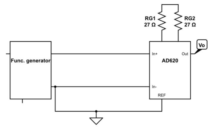
- I want to test the amplifier, by generating a 5 mV peak-peak sinusoid, send it into the in-amp and expect around 5 V peak-peak on the output. So I thought of using this setup: -
- 
However, my instructor suggests generating a 15 mV peak-peak sinusoid and using this setup instead: -- 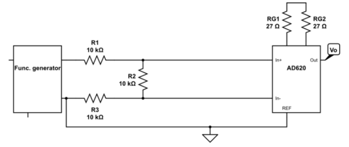
He said the setup was for creating a differential signal, but I am not sure why the first setup doesn't work.- **Question:** Why is the second setup needed to test my differential amplifier? What does the second setup do that the first one doesn't?
- I am using the [AD620 ](https://www.analog.com/media/en/technical-documentation/data-sheets/ad620.pdf)as instrumentation amplifier to amplify the body's ECG signal. An ECG is a differential signal (measured with two electrodes) and I want a differential gain of Gd=1000
- .
- The datasheet has this formula: $G_d=1+\frac{49.4 \: \text{k}Ω}{R_G}$
- , so using two resistors of 27 Ω
- gives me a gain of 916
- which is good enough.
- I want to test the amplifier, by generating a 5 mV peak-peak sinusoid, send it into the in-amp and expect around 5 V peak-peak on the output. So I thought of using this setup: -
- 
- My instructor suggests generating a 15 mV peak-peak sinusoid and using this setup instead: -
- 
- **Question:** Why is the second setup needed to test my differential amplifier? What does the second setup do that the first one doesn't?
#2: Post edited
by
Carl
·
2023-03-08T17:09:10Z (about 2 years ago)
I am using the AD620 as instrumentation amplifier to amplify the body's ECG signal. An ECG is a differential signal (measured with two electrodes) and I want a differential gain of Gd=1000- .
- The datasheet has this formula: $G_d=1+\frac{49.4 \: \text{k}Ω}{R_G}$
- , so using two resistors of 27 Ω
- gives me a gain of 916
- which is good enough.
- I want to test the amplifier, by generating a 5 mV peak-peak sinusoid, send it into the in-amp and expect around 5 V peak-peak on the output. So I thought of using this setup: -
- 
- However, my instructor suggests generating a 15 mV peak-peak sinusoid and using this setup instead: -
- 
- He said the setup was for creating a differential signal, but I am not sure why the first setup doesn't work.
- **Question:** Why is the second setup needed to test my differential amplifier? What does the second setup do that the first one doesn't?
- I am using the [AD620 ](https://www.analog.com/media/en/technical-documentation/data-sheets/ad620.pdf)as instrumentation amplifier to amplify the body's ECG signal. An ECG is a differential signal (measured with two electrodes) and I want a differential gain of Gd=1000
- .
- The datasheet has this formula: $G_d=1+\frac{49.4 \: \text{k}Ω}{R_G}$
- , so using two resistors of 27 Ω
- gives me a gain of 916
- which is good enough.
- I want to test the amplifier, by generating a 5 mV peak-peak sinusoid, send it into the in-amp and expect around 5 V peak-peak on the output. So I thought of using this setup: -
- 
- However, my instructor suggests generating a 15 mV peak-peak sinusoid and using this setup instead: -
- 
- He said the setup was for creating a differential signal, but I am not sure why the first setup doesn't work.
- **Question:** Why is the second setup needed to test my differential amplifier? What does the second setup do that the first one doesn't?
#1: Initial revision
by
Carl
·
2023-03-08T17:08:43Z (about 2 years ago)
Testing instrumentation amplifier with differential signal
I am using the AD620 as instrumentation amplifier to amplify the body's ECG signal. An ECG is a differential signal (measured with two electrodes) and I want a differential gain of Gd=1000
.
The datasheet has this formula: $G_d=1+\frac{49.4 \: \text{k}Ω}{R_G}$
, so using two resistors of 27 Ω
gives me a gain of 916
which is good enough.
I want to test the amplifier, by generating a 5 mV peak-peak sinusoid, send it into the in-amp and expect around 5 V peak-peak on the output. So I thought of using this setup: -

However, my instructor suggests generating a 15 mV peak-peak sinusoid and using this setup instead: -

He said the setup was for creating a differential signal, but I am not sure why the first setup doesn't work.
**Question:** Why is the second setup needed to test my differential amplifier? What does the second setup do that the first one doesn't?