Post History
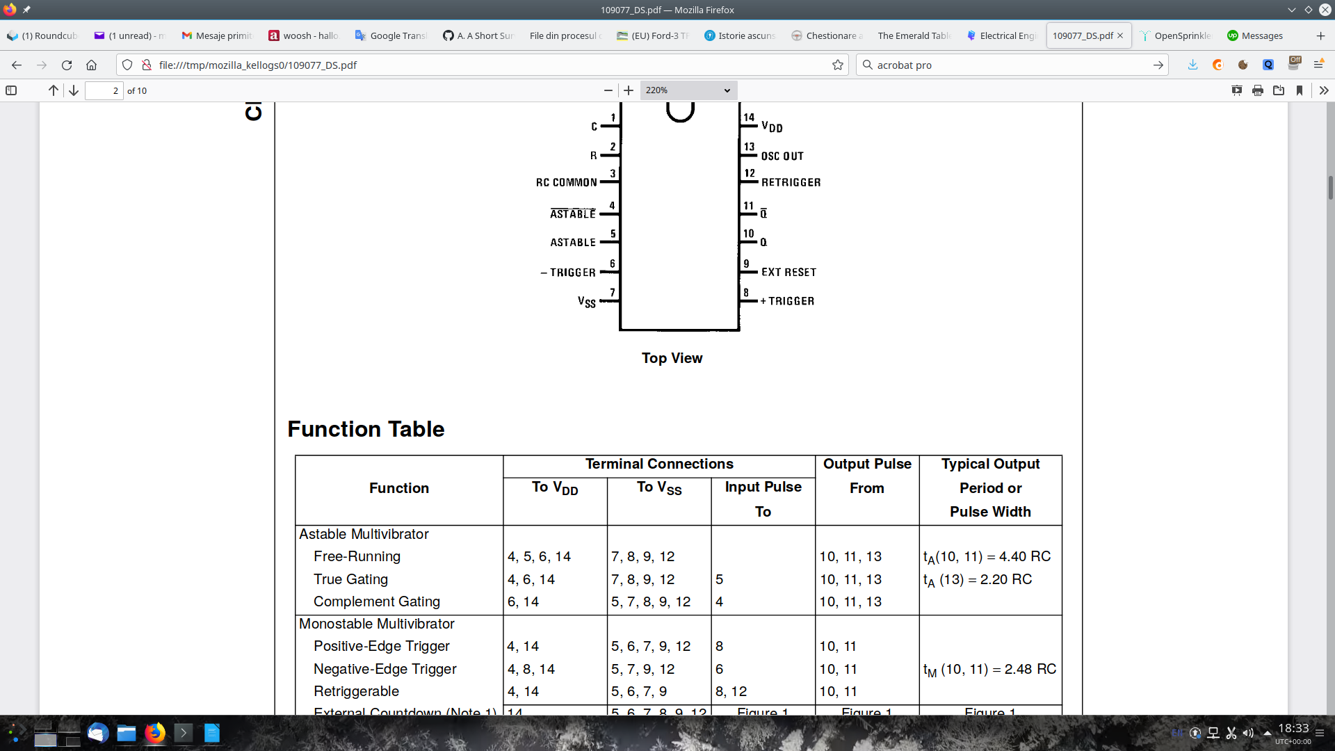
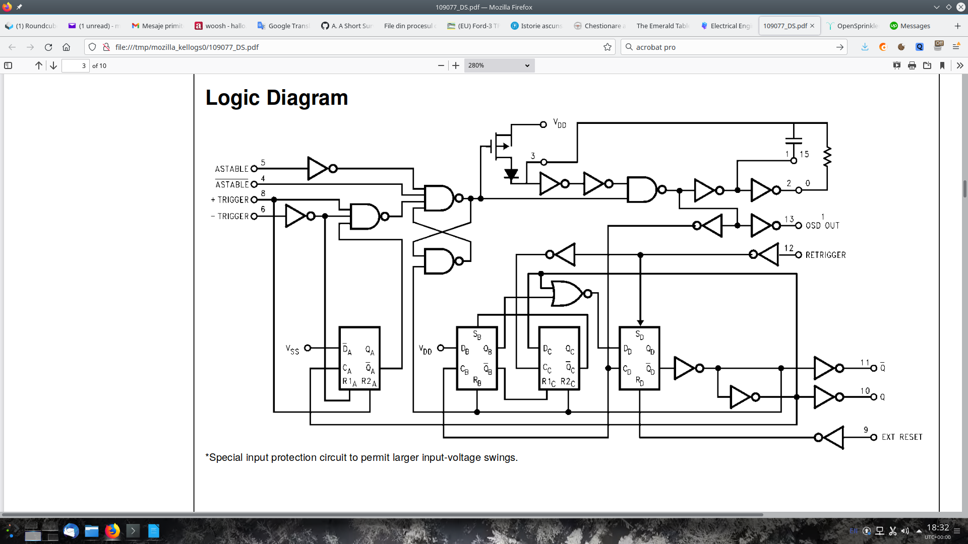
Hello, I am trying to use a CD4047 in monostable, positive-edge trigger mode: I am not skilled enough to make out what the output, i.e. pin 10, should be when pin 8, the input, is held at 0V (...
#5: Post edited
- Hello, I am trying to use a [`CD4047`](https://pdf1.alldatasheet.com/datasheet-pdf/view/26874/TI/CD4047.html) in monostable, positive-edge trigger mode:
- 
- 
- I am not skilled enough to make out what the output, i.e. pin 10, should be when pin 8, the input, is held at 0V (0.1V for some reason). Would expect it to be 0V, I am getting Vdd instead. Is this to be expected? Tried with two chips from different manufacturers bought from different stores.
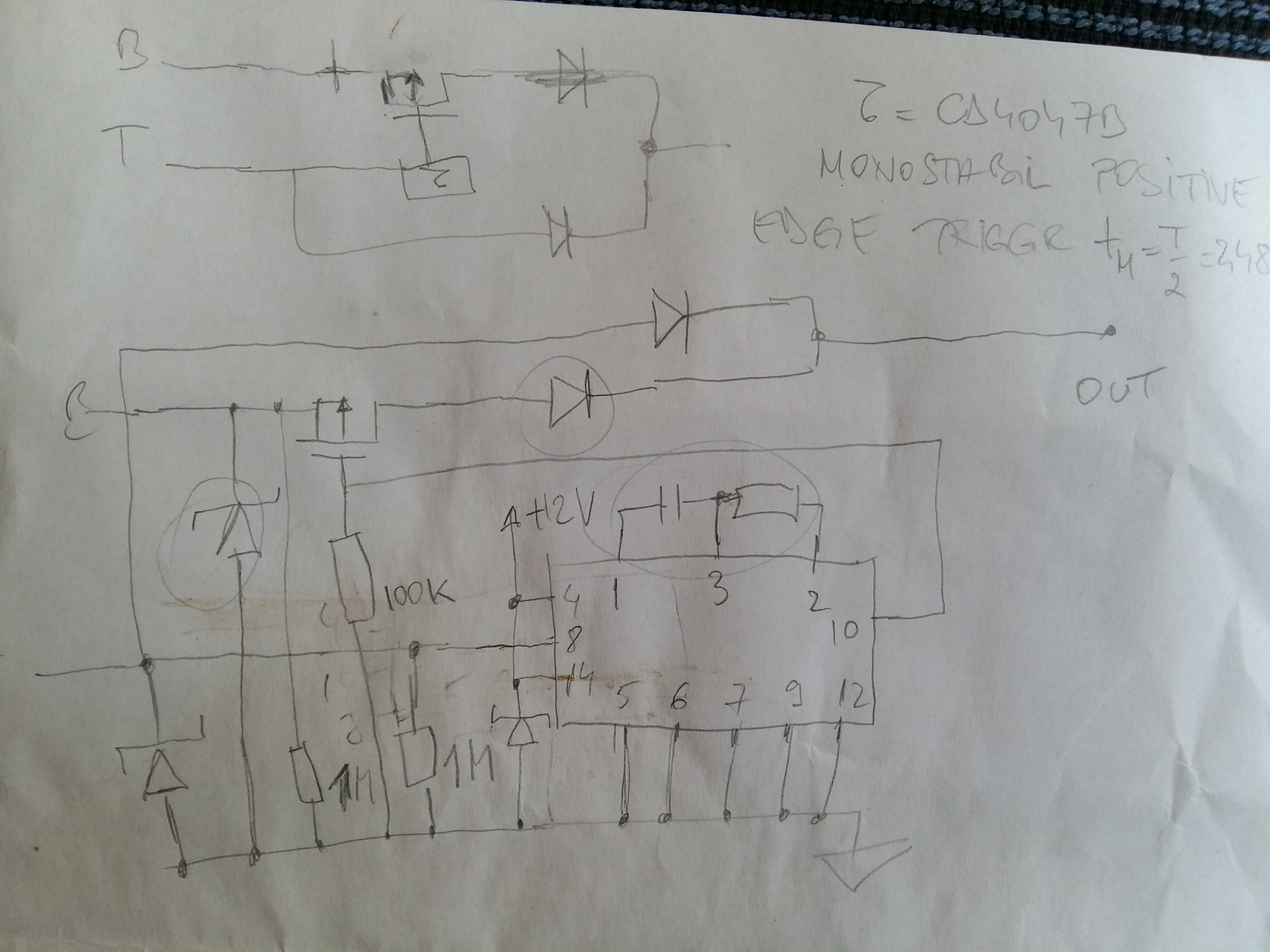
- My diagram:
- 
- P-MOSFET: [FQP17P06](https://pdf1.alldatasheet.com/datasheet-pdf/view/52341/FAIRCHILD/FQP17P06.html)
- TVS diodes: [P6KE18A](https://pdf1.alldatasheet.com/datasheet-pdf/view/59232/DIODES/P6KE18A.html)
- (Schottky) Diodes: [SBCT2040](https://pdf1.alldatasheet.com/datasheet-pdf/view/435178/DIOTEC/SBCT2040.html)
I am pretty sure everything has been wired correctly; tried on an Arduino UNO @ 5V and car battery @ 12V; I did measure pin 8, input, to be some 0.1 V in the absence of the T signal.
- Hello, I am trying to use a [`CD4047`](https://pdf1.alldatasheet.com/datasheet-pdf/view/26874/TI/CD4047.html) in monostable, positive-edge trigger mode:
- 
- 
- I am not skilled enough to make out what the output, i.e. pin 10, should be when pin 8, the input, is held at 0V (0.1V for some reason). Would expect it to be 0V, I am getting Vdd instead. Is this to be expected? Tried with two chips from different manufacturers bought from different stores.
- My diagram:
- 
- P-MOSFET: [FQP17P06](https://pdf1.alldatasheet.com/datasheet-pdf/view/52341/FAIRCHILD/FQP17P06.html)
- TVS diodes: [P6KE18A](https://pdf1.alldatasheet.com/datasheet-pdf/view/59232/DIODES/P6KE18A.html)
- (Schottky) Diodes: [SBCT2040](https://pdf1.alldatasheet.com/datasheet-pdf/view/435178/DIOTEC/SBCT2040.html)
- I am pretty sure everything has been wired correctly; tried on an Arduino UNO @ 5V and car battery @ 12V; I did measure pin 8, input, to be some 0.1 V in the absence of the T signal.
- -----
- This is getting quite weird. I have been poking at one of the circuit boards doing voltage measurements, putting the B and T signals to 0V / 5V / rectangular 0 -> 5V, it has started working as expected. I have then taken the second board, that one too has started to work as well. Some more fiddling later and only one kept working as expected.
- Some hours later and I think both chips are fine. Quitea few cold joints... I am going to retry them both PCBs on the 12V vehicle setup.
#4: Post edited
- Hello, I am trying to use a [`CD4047`](https://pdf1.alldatasheet.com/datasheet-pdf/view/26874/TI/CD4047.html) in monostable, positive-edge trigger mode:
- 
- 
- I am not skilled enough to make out what the output, i.e. pin 10, should be when pin 8, the input, is held at 0V (0.1V for some reason). Would expect it to be 0V, I am getting Vdd instead. Is this to be expected? Tried with two chips from different manufacturers bought from different stores.
- My diagram:
![Uploading, please wait...]()P-MOSFET:TVS diodes:Diodes:
- Hello, I am trying to use a [`CD4047`](https://pdf1.alldatasheet.com/datasheet-pdf/view/26874/TI/CD4047.html) in monostable, positive-edge trigger mode:
- 
- 
- I am not skilled enough to make out what the output, i.e. pin 10, should be when pin 8, the input, is held at 0V (0.1V for some reason). Would expect it to be 0V, I am getting Vdd instead. Is this to be expected? Tried with two chips from different manufacturers bought from different stores.
- My diagram:
- 
- P-MOSFET: [FQP17P06](https://pdf1.alldatasheet.com/datasheet-pdf/view/52341/FAIRCHILD/FQP17P06.html)
- TVS diodes: [P6KE18A](https://pdf1.alldatasheet.com/datasheet-pdf/view/59232/DIODES/P6KE18A.html)
- (Schottky) Diodes: [SBCT2040](https://pdf1.alldatasheet.com/datasheet-pdf/view/435178/DIOTEC/SBCT2040.html)
- I am pretty sure everything has been wired correctly; tried on an Arduino UNO @ 5V and car battery @ 12V; I did measure pin 8, input, to be some 0.1 V in the absence of the T signal.
#3: Post edited
Hello, I am trying to use a `CD4047` in monostable, positive-edge trigger mode:I am not skilled enough to make out what the output, i.e. pin 10, should be when pin 8, the input, is held at 0V (0.1V for some reason). Would expect it to be 0V, I am getting Vdd instead. Is this to be expected? Tried with two chips from different manufacturers bought from different stores.
- Hello, I am trying to use a [`CD4047`](https://pdf1.alldatasheet.com/datasheet-pdf/view/26874/TI/CD4047.html) in monostable, positive-edge trigger mode:
- 
- 
- I am not skilled enough to make out what the output, i.e. pin 10, should be when pin 8, the input, is held at 0V (0.1V for some reason). Would expect it to be 0V, I am getting Vdd instead. Is this to be expected? Tried with two chips from different manufacturers bought from different stores.
- My diagram:
- ![Uploading, please wait...]()
- P-MOSFET:
- TVS diodes:
- Diodes:
#2: Post edited
- Hello, I am trying to use a `CD4047` in monostable, positive-edge trigger mode:
- 
- 
I am not skilled enough to make out what the output should be when pin 8, the input, is 0V (0.1V for some reason). Would expect it to be 0V, I am getting Vdd instead. Is this to be expected? Tried with two chips from different manufacturers bought from different stores.
- Hello, I am trying to use a `CD4047` in monostable, positive-edge trigger mode:
- 
- 
- I am not skilled enough to make out what the output, i.e. pin 10, should be when pin 8, the input, is held at 0V (0.1V for some reason). Would expect it to be 0V, I am getting Vdd instead. Is this to be expected? Tried with two chips from different manufacturers bought from different stores.
#1: Initial revision
what should the output be for this use case of the CD4047 chip?
Hello, I am trying to use a `CD4047` in monostable, positive-edge trigger mode:   I am not skilled enough to make out what the output should be when pin 8, the input, is 0V (0.1V for some reason). Would expect it to be 0V, I am getting Vdd instead. Is this to be expected? Tried with two chips from different manufacturers bought from different stores.


