Post History
This IC is not well suited for the task. MPPT (Maximum Power Point Tracking) relies on matching impedance according to the maximum power transfer theorem. However, in the case of a photovoltaic ar...
#4: Post edited
by
 TonyStewart
·
2023-05-31T22:07:00Z (about 2 years ago)
TonyStewart
·
2023-05-31T22:07:00Z (about 2 years ago)
- This IC is not well suited for the task.
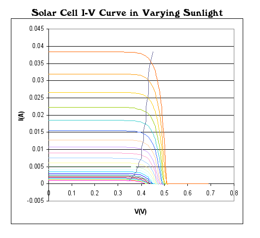
- MPPT (Maximum Power Point Tracking) relies on matching impedance according to the maximum power transfer theorem. However, in the case of a photovoltaic array (PV), it functions as a current source with a voltage limit (Voc) and a short circuit limit (Isc). The load line representing Voc/Isc=Rmpp, which is the effective incremental resistance at the maximum power point (MPP), is transferred due to the MPT theorem. However, unlike in 50 ohm systems with 50% loss, this is a current source, resulting in a different scenario.
- The incremental resistance is not Vmpp/Impp, but rather the derivative or slope of the V vs I curve at MPP.
- This information is not commonly taught, but is based on personal experience. It is worth noting for professors.
- If you refer to the quadratic points on the MPT curve on Wikipedia, you will find that at full sun, Vmpp/Voc is approximately 82%, and this drops to 72% at half sun. Therefore, if Voc=7.2V, 82% of this is 5.9V, which is close to the MPP voltage for full sun. Ideally, to transfer this current to a battery, a 5 to 6V battery without an MPP is desired.
- There are better plots but this shows the Voc, Ioc and MPP quadratic set of points. Take your Voc values and scale them to choose the % of Voc for the MPT point or MPP.
- You can use a suitable 6V battery to store enough energy for a few days then a MOSFET LDO with a much less than 0.5V min. dropout.
- This IC is not well suited for the task.
- MPPT (Maximum Power Point Tracking) relies on matching impedance according to the maximum power transfer theorem. However, in the case of a photovoltaic array (PV), it functions as a current source with a voltage limit (Voc) and a short circuit limit (Isc). The load line representing Voc/Isc=Rmpp, which is the effective incremental resistance at the maximum power point (MPP), is transferred due to the MPT theorem. However, unlike in 50 ohm systems with 50% loss, this is a current source, resulting in a different scenario.
- The incremental resistance is not Vmpp/Impp, but rather the derivative or slope of the V vs I curve at MPP.
- This information is not commonly taught, but is based on personal experience. It is worth noting for professors.
- If you refer to the quadratic points on the MPT curve on Wikipedia, you will find that at full sun, Vmpp/Voc is approximately 82%, and this drops to 72% at half sun. Therefore, if Voc=7.2V, 82% of this is 5.9V, which is close to the MPP voltage for full sun. Ideally, to transfer this current to a battery, a 5 to 6V battery without an MPP is desired.
- There are better plots but this shows the Voc, Ioc and MPP quadratic set of points. Take your Voc values and scale them to choose the % of Voc for the MPT point or MPP.
- You can use a suitable 6V battery to store enough energy for a few days then a MOSFET LDO with a much less than 0.5V min. dropout.
- 
- What this means is you average solar current, voltage or power must exceed the average load of your application to sustain 5V. There is no lossy tracking of MPPT but rather using the best 5 to 6.5V battery to store linear charging and then never draw more average energy than being supplied. The LDO ought to have a heatsink if you need a power burst that raises it's temperature and use your Thermodynamic thermal resistance rules.
- For a 150 mA PV array, I think this is a sensible open loop design.
#3: Post edited
by
TonyStewart
·
2023-05-31T22:01:27Z (about 2 years ago)
- This IC is not well suited for the task.
- MPPT (Maximum Power Point Tracking) relies on matching impedance according to the maximum power transfer theorem. However, in the case of a photovoltaic array (PV), it functions as a current source with a voltage limit (Voc) and a short circuit limit (Isc). The load line representing Voc/Isc=Rmpp, which is the effective incremental resistance at the maximum power point (MPP), is transferred due to the MPT theorem. However, unlike in 50 ohm systems with 50% loss, this is a current source, resulting in a different scenario.
- The incremental resistance is not Vmpp/Impp, but rather the derivative or slope of the V vs I curve at MPP.
- This information is not commonly taught, but is based on personal experience. It is worth noting for professors.
- If you refer to the quadratic points on the MPT curve on Wikipedia, you will find that at full sun, Vmpp/Voc is approximately 82%, and this drops to 72% at half sun. Therefore, if Voc=7.2V, 82% of this is 5.9V, which is close to the MPP voltage for full sun. Ideally, to transfer this current to a battery, a 5 to 6V battery without an MPP is desired.
- There are better plots but this shows the Voc, Ioc and MPP quadratic set of points. Take your Voc values and scale them to choose the % of Voc for the MPT point or MPP.
You can use a suitable 6V battery to store enough energy for a few days then a MOSFET LDO witha 0.5V min. dropout.- 
- This IC is not well suited for the task.
- MPPT (Maximum Power Point Tracking) relies on matching impedance according to the maximum power transfer theorem. However, in the case of a photovoltaic array (PV), it functions as a current source with a voltage limit (Voc) and a short circuit limit (Isc). The load line representing Voc/Isc=Rmpp, which is the effective incremental resistance at the maximum power point (MPP), is transferred due to the MPT theorem. However, unlike in 50 ohm systems with 50% loss, this is a current source, resulting in a different scenario.
- The incremental resistance is not Vmpp/Impp, but rather the derivative or slope of the V vs I curve at MPP.
- This information is not commonly taught, but is based on personal experience. It is worth noting for professors.
- If you refer to the quadratic points on the MPT curve on Wikipedia, you will find that at full sun, Vmpp/Voc is approximately 82%, and this drops to 72% at half sun. Therefore, if Voc=7.2V, 82% of this is 5.9V, which is close to the MPP voltage for full sun. Ideally, to transfer this current to a battery, a 5 to 6V battery without an MPP is desired.
- There are better plots but this shows the Voc, Ioc and MPP quadratic set of points. Take your Voc values and scale them to choose the % of Voc for the MPT point or MPP.
- You can use a suitable 6V battery to store enough energy for a few days then a MOSFET LDO with a much less than 0.5V min. dropout.
- 
#2: Post edited
by
TonyStewart
·
2023-05-31T22:00:45Z (about 2 years ago)
- This IC is not well suited for the task.
- MPPT (Maximum Power Point Tracking) relies on matching impedance according to the maximum power transfer theorem. However, in the case of a photovoltaic array (PV), it functions as a current source with a voltage limit (Voc) and a short circuit limit (Isc). The load line representing Voc/Isc=Rmpp, which is the effective incremental resistance at the maximum power point (MPP), is transferred due to the MPT theorem. However, unlike in 50 ohm systems with 50% loss, this is a current source, resulting in a different scenario.
- The incremental resistance is not Vmpp/Impp, but rather the derivative or slope of the V vs I curve at MPP.
- This information is not commonly taught, but is based on personal experience. It is worth noting for professors.
- If you refer to the quadratic points on the MPT curve on Wikipedia, you will find that at full sun, Vmpp/Voc is approximately 82%, and this drops to 72% at half sun. Therefore, if Voc=7.2V, 82% of this is 5.9V, which is close to the MPP voltage for full sun. Ideally, to transfer this current to a battery, a 5 to 6V battery without an MPP is desired.
There are better plots but this shows the Voc, Ioc and MPP quadratic set of points. Take your Voc values and scale them to choose the % of Voc for the MPT point or MPP.- 
- This IC is not well suited for the task.
- MPPT (Maximum Power Point Tracking) relies on matching impedance according to the maximum power transfer theorem. However, in the case of a photovoltaic array (PV), it functions as a current source with a voltage limit (Voc) and a short circuit limit (Isc). The load line representing Voc/Isc=Rmpp, which is the effective incremental resistance at the maximum power point (MPP), is transferred due to the MPT theorem. However, unlike in 50 ohm systems with 50% loss, this is a current source, resulting in a different scenario.
- The incremental resistance is not Vmpp/Impp, but rather the derivative or slope of the V vs I curve at MPP.
- This information is not commonly taught, but is based on personal experience. It is worth noting for professors.
- If you refer to the quadratic points on the MPT curve on Wikipedia, you will find that at full sun, Vmpp/Voc is approximately 82%, and this drops to 72% at half sun. Therefore, if Voc=7.2V, 82% of this is 5.9V, which is close to the MPP voltage for full sun. Ideally, to transfer this current to a battery, a 5 to 6V battery without an MPP is desired.
- There are better plots but this shows the Voc, Ioc and MPP quadratic set of points. Take your Voc values and scale them to choose the % of Voc for the MPT point or MPP.
- You can use a suitable 6V battery to store enough energy for a few days then a MOSFET LDO witha 0.5V min. dropout.
- 
#1: Initial revision
by
TonyStewart
·
2023-05-31T21:57:29Z (about 2 years ago)
This IC is not well suited for the task. MPPT (Maximum Power Point Tracking) relies on matching impedance according to the maximum power transfer theorem. However, in the case of a photovoltaic array (PV), it functions as a current source with a voltage limit (Voc) and a short circuit limit (Isc). The load line representing Voc/Isc=Rmpp, which is the effective incremental resistance at the maximum power point (MPP), is transferred due to the MPT theorem. However, unlike in 50 ohm systems with 50% loss, this is a current source, resulting in a different scenario. The incremental resistance is not Vmpp/Impp, but rather the derivative or slope of the V vs I curve at MPP. This information is not commonly taught, but is based on personal experience. It is worth noting for professors. If you refer to the quadratic points on the MPT curve on Wikipedia, you will find that at full sun, Vmpp/Voc is approximately 82%, and this drops to 72% at half sun. Therefore, if Voc=7.2V, 82% of this is 5.9V, which is close to the MPP voltage for full sun. Ideally, to transfer this current to a battery, a 5 to 6V battery without an MPP is desired. There are better plots but this shows the Voc, Ioc and MPP quadratic set of points. Take your Voc values and scale them to choose the % of Voc for the MPT point or MPP. 