Post History
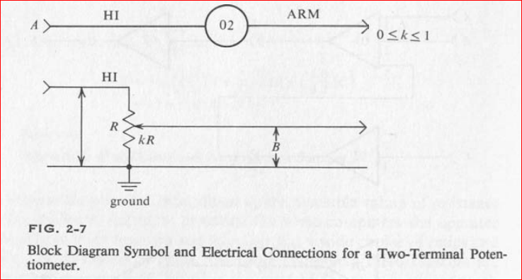
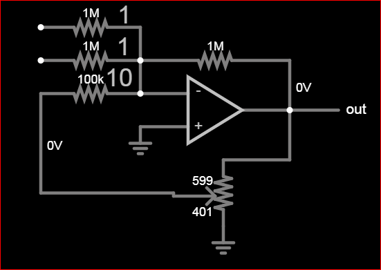
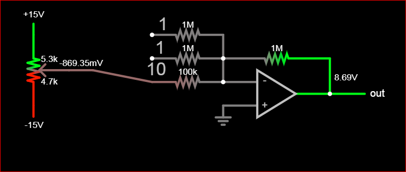
The two-terminal symbol for the attenuator comes from 3 pin potentiometer (pot.) referenced to 0V = "GND" The summing amplifier is always inverting and gives you 3 options for gain which means i...
#6: Post edited
by
 TonyStewart
·
2023-06-04T12:54:33Z (about 2 years ago)
TonyStewart
·
2023-06-04T12:54:33Z (about 2 years ago)
- The two-terminal symbol for the attenuator comes from 3 pin potentiometer (pot.) referenced to 0V = "GND"
- 
- The summing amplifier is always inverting and gives you 3 options for gain which means internally it uses a 3 pin pot. to choose the gain for you based on the ratio of resistance from output to input side.
- So when you choose an input like 10, does it make sense to choose another gain input in parallel? (no). You do need to chose an input since your block diagram shows no other input.
- Since you have no input (=0) to a gain input(=-10) and feedback of 0.4 , your output should be 0 * (-10) * 0.4 = 0
- 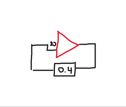
- What you show looks something like this.
- 
- Since your question is also confusing without expectations or purpose, perhaps you are trying to take a ratio between Vcc and Vee and then connect that scope measured value to the inverting sum amp.
- like this:
- 
#5: Post edited
by
TonyStewart
·
2023-06-04T12:29:12Z (about 2 years ago)
- The two-terminal symbol for the attenuator comes from 3 pin potentiometer (pot.) referenced to 0V = "GND"
- 
- The summing amplifier is always inverting and gives you 3 options for gain which means internally it uses a 3 pin pot. to choose the gain for you based on the ratio of resistance from output to input side.
- So when you choose an input like 10, does it make sense to choose another gain input in parallel? (no). You do need to chose an input since your block diagram shows no other input.
- Since you have no input (=0) to a gain input(=-10) and feedback of 0.4 , your output should be 0 * (-10) * 0.4 = 0
- 
- What you show looks something like this.
- 
#4: Post edited
by
TonyStewart
·
2023-06-04T12:28:35Z (about 2 years ago)
- The two-terminal symbol for the attenuator comes from 3 pin potentiometer (pot.) referenced to 0V = "GND"
- 
- The summing amplifier is always inverting and gives you 3 options for gain which means internally it uses a 3 pin pot. to choose the gain for you based on the ratio of resistance from output to input side.
- So when you choose an input like 10, does it make sense to choose another gain input in parallel? (no). You do need to chose an input since your block diagram shows no other input.
- Since you have no input (=0) to a gain input(=-10) and feedback of 0.4 , your output should be 0 * (-10) * 0.4 = 0
- What you show looks something like this.
- 
- The two-terminal symbol for the attenuator comes from 3 pin potentiometer (pot.) referenced to 0V = "GND"
- 
- The summing amplifier is always inverting and gives you 3 options for gain which means internally it uses a 3 pin pot. to choose the gain for you based on the ratio of resistance from output to input side.
- So when you choose an input like 10, does it make sense to choose another gain input in parallel? (no). You do need to chose an input since your block diagram shows no other input.
- Since you have no input (=0) to a gain input(=-10) and feedback of 0.4 , your output should be 0 * (-10) * 0.4 = 0
- 
- What you show looks something like this.
- 
#3: Post edited
by
TonyStewart
·
2023-06-04T12:18:03Z (about 2 years ago)
- The two-terminal symbol for the attenuator comes from 3 pin potentiometer (pot.) referenced to 0V = "GND"
- 
- The summing amplifier is always inverting and gives you 3 options for gain which means internally it uses a 3 pin pot. to choose the gain for you based on the ratio of resistance from output to input side.
- So when you choose an input like 10, does it make sense to choose another gain input in parallel? (no). You do need to chose an input since your block diagram shows no other input.
Since you have no input (=0) to a gain input(=-10) and feedback of 0.4 , your output should be 0 * (-10) * 0.4 = 0
- The two-terminal symbol for the attenuator comes from 3 pin potentiometer (pot.) referenced to 0V = "GND"
- 
- The summing amplifier is always inverting and gives you 3 options for gain which means internally it uses a 3 pin pot. to choose the gain for you based on the ratio of resistance from output to input side.
- So when you choose an input like 10, does it make sense to choose another gain input in parallel? (no). You do need to chose an input since your block diagram shows no other input.
- Since you have no input (=0) to a gain input(=-10) and feedback of 0.4 , your output should be 0 * (-10) * 0.4 = 0
- What you show looks something like this.
- 
#2: Post edited
by
TonyStewart
·
2023-06-04T12:07:12Z (about 2 years ago)
- The two-terminal symbol for the attenuator comes from 3 pin potentiometer (pot.) referenced to 0V = "GND"
- 
- The summing amplifier is always inverting and gives you 3 options for gain which means internally it uses a 3 pin pot. to choose the gain for you based on the ratio of resistance from output to input side.
So when you choose an input like 10, does it make sense to choose another gain input in parallel? (no). You do need to chose an input since your block diagram shows no input.**Since you have no input (0) to gain input(-10) and feedback of 0.4 , your output should be 0 * (-10) * 0.4 = 0
- The two-terminal symbol for the attenuator comes from 3 pin potentiometer (pot.) referenced to 0V = "GND"
- 
- The summing amplifier is always inverting and gives you 3 options for gain which means internally it uses a 3 pin pot. to choose the gain for you based on the ratio of resistance from output to input side.
- So when you choose an input like 10, does it make sense to choose another gain input in parallel? (no). You do need to chose an input since your block diagram shows no other input.
- Since you have no input (=0) to a gain input(=-10) and feedback of 0.4 , your output should be 0 * (-10) * 0.4 = 0
#1: Initial revision
by
TonyStewart
·
2023-06-04T12:05:13Z (about 2 years ago)
The two-terminal symbol for the attenuator comes from 3 pin potentiometer (pot.) referenced to 0V = "GND"  The summing amplifier is always inverting and gives you 3 options for gain which means internally it uses a 3 pin pot. to choose the gain for you based on the ratio of resistance from output to input side. So when you choose an input like 10, does it make sense to choose another gain input in parallel? (no). You do need to chose an input since your block diagram shows no input.** Since you have no input (0) to gain input(-10) and feedback of 0.4 , your output should be 0 * (-10) * 0.4 = 0