Power switches and automotive load dump, unclamped
Power switches used in automotive are usually rated to withstand clamped load dump events, of the 35 - 40 V peak variety. AFAICT there are two main clamping mechanisms - first one for the logic part and second one for the MOSFET DS channel within. These power switches will generally (re)open the DS channel once the second clamping mechanism has engaged.
Since manufacturers do not boast about their power switches being able to withstand full (unclamped) load dumps it must be the case that the FETs within won't take that kind of energy / peak power.
Worst case as per ISO 16750-2: Ri = 0.5 ohm, Vs = 79 V, tr = 5 ms, td = 400 ms. Could I use some TVS diodes effectively for protecting against this ?
My targeted power switches Rds(on) = 30 - 40 mohm and for a led light of 200 mA normal draw @ 12V I would throw in 60 ohm of dynamic reistance even for voltage spikes (?).
My targeted TVS dynamic resistance Rd = 1/Pdc +/- 50% ~= 1/8 = 125 mohm (formula pricked up from here). Multiply that by 3 for a stack of 3 TVS diodes -> 375 mohm.
It appears at a first glance that the TVS stack is sufficient to help out a power switch make it through load dump events unharmed. Of course, the logic part must also tolerate the clamping voltage of these 3 series TVS diodes. Does anything escape my thinking ?
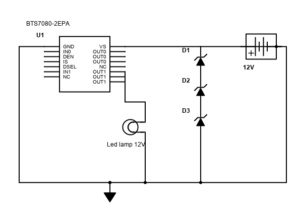
edit Diagram:
2 answers
It seems you want to protect a device against power spikes. The power supply is nominally 12 V, but can have spikes up to 79 V with an impedance of 500 mΩ. Two timing values were given, but they are useless without being defined, so we can only ignore them. The device can draw up to 200 mA. You want to know whether TVS clamps can be used to suitably protect the device.
The first thing you need to determine is what voltages the device can tolerate. That may depend on whether it still needs to operate during a power spike. If it just has to survive, then the absolute maximum input voltage is the relevant spec. If it needs to continue operating, then the maximum operating voltage is what matters.
You also need to know the minimum voltage the device needs for normal operation.
Since you haven't specified any of this, I'll make up values to use for illustration purposes only. It's your job to check the datasheet to find the real values, then re-run the calculations.
Since you say this is a 12 V automotive application, let's say the normal power voltage can be from 11 to 15 V. Let's also say the device can operate normally from 10 to 20 V.
A clamp needs some impedance to work against. A clamp on an ideal voltage source only causes lots of current when clamping, and doesn't cause the voltage to change any. You do say that these spikes have 500 mΩ impedance. That's not much, so some additional deliberate impedance would be helpful.
Since the lowest normal power voltage is 11 V and the device can work down to 10 V, you can afford to drop up to 1 V. At the maximum current draw of 200 mA, the maximum series resistance you can add is (1 V)/(200 mA) = 5 Ω. That's right at the limit, so less should be added. Let's pick 2 Ω deliberate resistance to put in series with the power supply.
Now let's see what a clamp needs to do to limit a spike to safe levels. The Thevenin equivalent of a spike is now 79 V at 2.5 Ω. To bring that down to 20 V, the clamp must draw (59 V)/(2.5 Ω) = 23.6 A. So the first spec is that the clamp must be capable of 25 A surge current. You also have to check that it can handle this for whatever the maximum duration of a spike is. In addition, you have to check that the total average dissipation is within spec given the maximum repetition rate of spikes.
Let's say spikes can last 100 ms and can occur every 2 seconds (example numbers only, your job to find the real values). During the spike, the clamp dissipates (23.6 A)(20 V) = 472 W. That times the duration means the clamp must dissipate 47.2 J each event. The average dissipation at 2 second repetition rate is 24 W. That's quite beefy and will take some size and cost.
The above is based on made-up numbers. You have to redo the calculations with the real duration and repetition rate. However, if they are anything close to the example values, that will be a very large clamp. That argues for looking more closely at series protection in addition to or instead of shunt protection. At these levels, it is beneficial to avoid taking the power rather than dissipating it.
Another possibility is temporary storage of the spike energy instead of dissipating it. This looks intractable for the levels assumed in the example, but I'll do the math to illustrate the concept anyway.
Let's say you have a 1 mF capacitor after the 2 Ω series resistance. The time constant is (2.5 Ω)(1 mF) = 2.5 ms. To go from 15 V to 20 V with 79 V applied takes 0.29 time constants, or 720 µs. You'd need to cap 139 times larger, or 139 mF to be able to ride out the whole 100 ms spike. That's unrealistically large, but the point was to show how this concept works.
It's pointless to continue without specs on the duration and repetition rate of the spikes, but at first glance it looks like series protection should really be considered.
0 comment threads
The spec 79V 0.5 ohm 5ms = 62.41 Joules . The TVS must be rated for a low temp. rise at this energy dump or higher.
MOV's are limited by the number of discharges as the oxide wears out, but may be used if size appropriately for desired MTBF.
0 comment threads


1 comment thread