Post History
Let's take a soft-start circuit that looks like this: To my understanding, the function can be described as follows: C1 charges to open the gate. Value of C1 will dictate the soft-start delay...
#2: Post edited
by
 Mu3
·
2023-08-31T14:18:03Z (almost 2 years ago)
Mu3
·
2023-08-31T14:18:03Z (almost 2 years ago)
- Let's take a soft-start circuit that looks like this:
- 
- To my understanding, the function can be described as follows:
- - C1 charges to open the gate. Value of C1 will dictate the soft-start delay.
- - R2 and R1 form a divider that establishes a bias on the gate voltage once the FET opens.
- R1 also serves to discharge C1 after input voltage is removed.- This circuit works in simulation and in the real world.
- 
- Here, $V_{in}$ in the input voltage, $V_{out}$ the output, and $V_{n001}$ in the gate voltage of the FET. $V_{n001}-V_{in}$ is then the gate-source voltage.
- The capacitor starts charging and at a certain point a sufficient $V_{gs}$ is reached after which the FET will begin to open. This is clearly seen on the simulation. However, I am not certain why the R2/R1 divider is at all necessary since the soft-start fucntionality is achieved through the R1/C1 circuit.
- Therefore the question: what is the point of using R2 in this circuit?
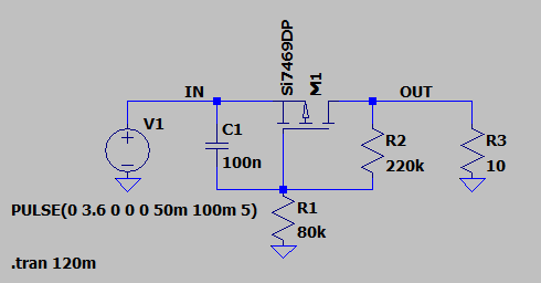
- Let's take a soft-start circuit that looks like this:
- 
- To my understanding, the function can be described as follows:
- - C1 charges to open the gate. Value of C1 will dictate the soft-start delay.
- - R2 and R1 form a divider that establishes a bias on the gate voltage once the FET opens.
- - R1 also dictates startup time and serves to discharge C1 after input voltage is removed.
- This circuit works in simulation and in the real world.
- 
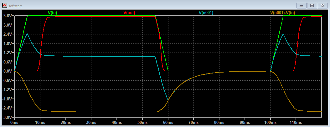
- Here, $V_{in}$ in the input voltage, $V_{out}$ the output, and $V_{n001}$ in the gate voltage of the FET. $V_{n001}-V_{in}$ is then the gate-source voltage.
- The capacitor starts charging and at a certain point a sufficient $V_{gs}$ is reached after which the FET will begin to open. This is clearly seen on the simulation. However, I am not certain why the R2/R1 divider is at all necessary since the soft-start fucntionality is achieved through the R1/C1 circuit.
- Therefore the question: what is the point of using R2 in this circuit?
#1: Initial revision
by
Mu3
·
2023-08-31T14:14:37Z (almost 2 years ago)
Soft-start circuit behaviour
Let's take a soft-start circuit that looks like this:

To my understanding, the function can be described as follows:
- C1 charges to open the gate. Value of C1 will dictate the soft-start delay.
- R2 and R1 form a divider that establishes a bias on the gate voltage once the FET opens.
- R1 also serves to discharge C1 after input voltage is removed.
This circuit works in simulation and in the real world.

Here, $V_{in}$ in the input voltage, $V_{out}$ the output, and $V_{n001}$ in the gate voltage of the FET. $V_{n001}-V_{in}$ is then the gate-source voltage.
The capacitor starts charging and at a certain point a sufficient $V_{gs}$ is reached after which the FET will begin to open. This is clearly seen on the simulation. However, I am not certain why the R2/R1 divider is at all necessary since the soft-start fucntionality is achieved through the R1/C1 circuit.
Therefore the question: what is the point of using R2 in this circuit?