Post History
Which topology is preferable? The one below because the LED driver is less likely to produce instability and, if it does, you can always tweak C4 (upwards) in order to kill-off the potentially...
#6: Post edited
by
 Andy aka
·
2024-03-16T18:46:33Z (over 1 year ago)
Andy aka
·
2024-03-16T18:46:33Z (over 1 year ago)
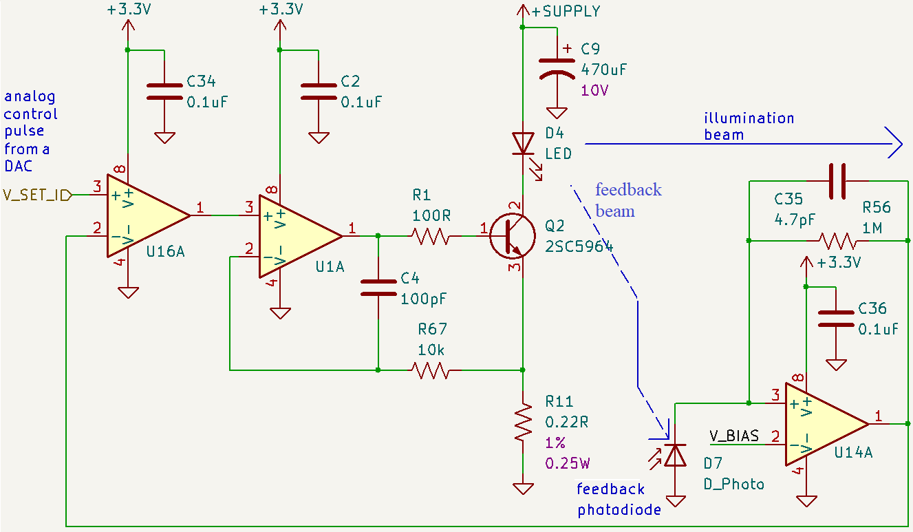
- > _Which topology is preferable?_
- The one below because the LED driver is less likely to produce instability and, if it does, you can always tweak C4 (upwards) in order to kill-off the potentially oscillatory pole produced in the response in your first circuit.
- How to draw schematics that provide decent visual definition: -
In other words concentrate on making an image that can be viewed easily without opening it up in a separate tab. You could make it even more readable (than my cut n paste version) with a little care.
- > _Which topology is preferable?_
- The one below because the LED driver is less likely to produce instability and, if it does, you can always tweak C4 (upwards) in order to kill-off the potentially oscillatory pole produced in the response in your first circuit.
- How to draw schematics that provide decent visual definition: -
- 
- So, concentrate on making an image that can be easily viewed without opening it in a separate tab. You could make it even more readable (than my cut n paste version) with a little care.
#5: Post edited
by
Andy aka
·
2024-03-16T18:07:36Z (over 1 year ago)
- > _Which topology is preferable?_
- The one below because the LED driver is less likely to produce instability and, if it does, you can always tweak C4 (upwards) in order to kill-off the potentially oscillatory pole produced in the response in your first circuit.
- How to draw schematics that provide decent visual definition: -
- In other words concentrate on making an image that can be viewed easily without opening it up in a separate tab. You could make it even more readable (than my cut n paste version) with a little care.
- > _Which topology is preferable?_
- The one below because the LED driver is less likely to produce instability and, if it does, you can always tweak C4 (upwards) in order to kill-off the potentially oscillatory pole produced in the response in your first circuit.
- How to draw schematics that provide decent visual definition: -
- 
- In other words concentrate on making an image that can be viewed easily without opening it up in a separate tab. You could make it even more readable (than my cut n paste version) with a little care.
#4: Post edited
by
Andy aka
·
2024-03-16T16:58:36Z (over 1 year ago)
- > _Which topology is preferable?_
- The one below because the LED driver is less likely to produce instability and, if it does, you can always tweak C4 (upwards) in order to kill-off the potentially oscillatory pole produced in the response in your first circuit.
- How to draw schematics that provide decent visual definition: -
- 
In other words concentrate and making an image that can be viewed easily without opening it up in a separate tab. You could make it even more readable (than my cut n paste version) with a little care.
- > _Which topology is preferable?_
- The one below because the LED driver is less likely to produce instability and, if it does, you can always tweak C4 (upwards) in order to kill-off the potentially oscillatory pole produced in the response in your first circuit.
- How to draw schematics that provide decent visual definition: -
- 
- In other words concentrate on making an image that can be viewed easily without opening it up in a separate tab. You could make it even more readable (than my cut n paste version) with a little care.
#3: Post edited
by
Andy aka
·
2024-03-16T16:58:03Z (over 1 year ago)
**Please don't vote on this answer**How to draw schematics that provide decent visual definition: -- 
- In other words concentrate and making an image that can be viewed easily without opening it up in a separate tab. You could make it even more readable (than my cut n paste version) with a little care.
- > _Which topology is preferable?_
- The one below because the LED driver is less likely to produce instability and, if it does, you can always tweak C4 (upwards) in order to kill-off the potentially oscillatory pole produced in the response in your first circuit.
- How to draw schematics that provide decent visual definition: -
- 
- In other words concentrate and making an image that can be viewed easily without opening it up in a separate tab. You could make it even more readable (than my cut n paste version) with a little care.
#2: Post edited
by
Andy aka
·
2024-03-16T16:54:57Z (over 1 year ago)
Information on drawing schematics that provide sufficient definition on this website: -- In other words concentrate and making an image that can be viewed easily without opening it up in a separate tab. You could make it even more readable (than my cut n paste version) with a little care.
- **Please don't vote on this answer**
- How to draw schematics that provide decent visual definition: -
- 
- In other words concentrate and making an image that can be viewed easily without opening it up in a separate tab. You could make it even more readable (than my cut n paste version) with a little care.
#1: Initial revision
by
Andy aka
·
2024-03-16T16:46:04Z (over 1 year ago)
Information on drawing schematics that provide sufficient definition on this website: -  In other words concentrate and making an image that can be viewed easily without opening it up in a separate tab. You could make it even more readable (than my cut n paste version) with a little care.