How do I design a boost converter? What are the basics I should know?
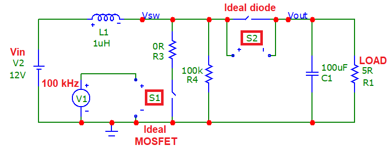
I need to design a simple boost converter like this: -
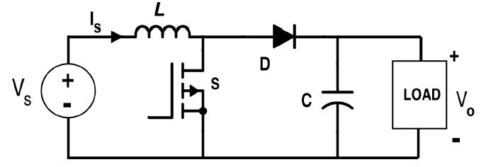
I want to control duty cycle from another circuit such as an MCU but, I'm unsure how to proceed. My requirements are: -
- Input voltage 12 volts
- Output voltage 16 volts
- Load resistance is 5 ohms
- Inductor 1μH
- Operating frequency 100 kHz
1 answer
An on-line boost converter calculator
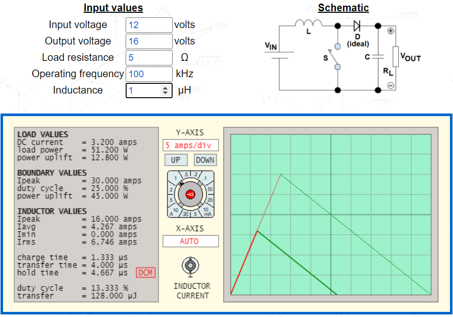
Image from this website.
The Operating Mode
The circuit operates in either of two modes but, the voltage transfer equation is different for each mode. Therefore, you need to establish the operating mode before you can calculate duty cycle. The operating modes are: -
- DCM (discontinuous conduction mode) - inductor current will fall to zero amps. Accommodates light to medium load currents. Duty cycle lower than CCM.
- CCM (continuous conduction mode) - inductor current remains above zero amps. Accommodates medium to heavier load currents. Duty cycle higher than DCM.
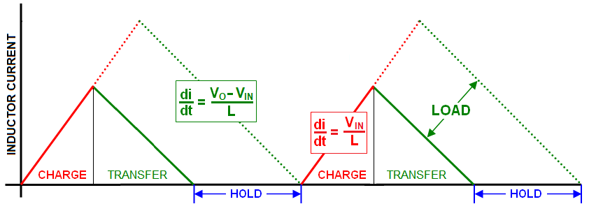
DCM has three distinct phases per switching cycle; charge, transfer and hold. The length of the hold-phase accommodates load current variations: -
-
The"hold" phase begins when the all the inductor's energy is transferred to the load. If the load "demands" more energy/power, then the "hold" phase must shorten and the charge phase lengthen. If the load requires less energy, then the "hold" phase increases.
- Therefore, in order to maintain the desired output voltage, the duty cycle has to be continually adjusted to accommodate load current changes.
-
The slopes of the currents ($\frac{di}{dt}$) are non-negotiable because they define the input and output voltages as per Faraday's law of induction.
- If the input voltage reduced by 10% then the current charge slope (red) also must reduce by 10%.
- If the output voltage requirement increased by 20% then the current transfer slope (green) must also increase by 20%.
- If the input voltage changes, duty cycle must also be adjusted to maintain the correct output voltage for a given load current. This is also true for CCM operation.
-
If the hold-phase becomes zero and the load current demand is still rising, DCM will "slip into" CCM. This can cause output voltage instability.
CCM has just two phases; charge and transfer. Load current changes are accommodated by the whole of the inductor current waveform rising or falling: -
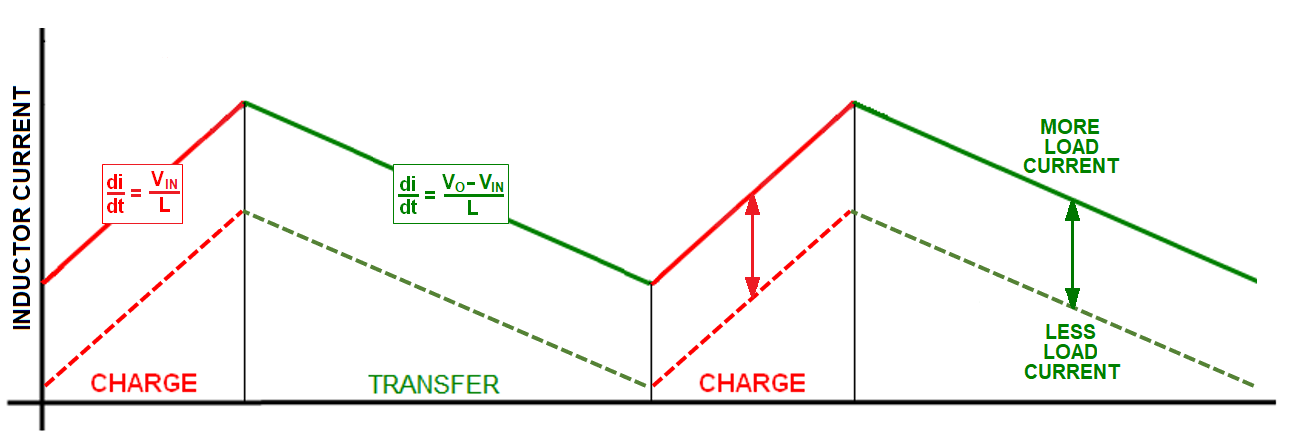
CCM doesn't have a "hold" phase because it's continually charging and transferring energy however, here's a reminder: -
$$\color{red}{\boxed{\large{\text{ CCM and DCM have different voltage transfer equations }}\normalsize}}$$
This means that for a given load and duty cycle, DCM won't deliver the same output voltage as CCM. This is an important distinction.
CCM and DCM summary
- Only one mode will deliver 16 volts to the 5 Ω load with $V_{IN}$, $L$ and $F_{SW}$ as specified.
- Lighter loads are usually serviced in DCM
- Heavier loads are usually serviced in CCM
- CCM is a natural outcome when DCM can't service the heavier load
- DCM is a natural outcome when CCM can't service the lighter load
The next step is to decide which operating mode fulfills the requirements of the proposed design.
To perform this next step we consider the boundary condition. This is where DCM meets CCM; the inductor has delivered all it's energy to the output and the switching cycle restarts immediately. We then need to ask this hypothetical question: -
$$\color{red}{\boxed{\large{\text{At the boundary, is the load power sufficient to sustain } V_{OUT}?}\normalsize}}$$
If the answer is yes, then we will operate in DCM. If the answer is no we will operate in CCM.
Boundary condition
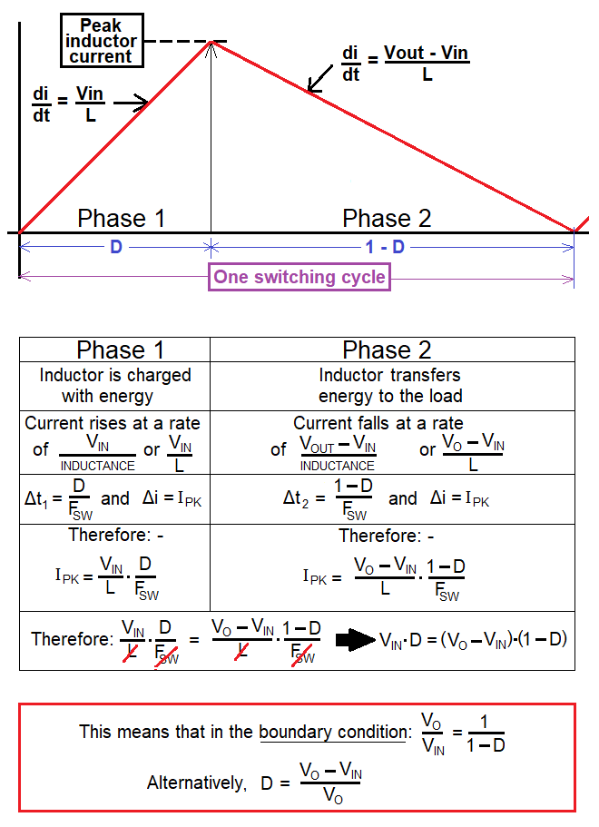
Right at the bottom of the picture is an important formula: -
$$\boxed{D = \dfrac{V_O - V_{IN}}{V_O}}$$
So, let's calculate it using the numbers in the question: -
$$D = \dfrac{\text{16 volts - 12 volts }}{\text{16 volts}} = 0.25$$
This means that the time taken for phase 1 to complete ($t_1$) is: -
$$t_1 = \dfrac{D}{F_{SW}} = \dfrac{0.25}{100\text{ kHz}} = 2.5\text{ μs}$$
Knowing $t_1$ we then ask this question: -
Can we acquire enough energy in the inductor to sustain the 5 Ω load at 16 volts with a charge time of 2.5 μs? To answer this we must find the peak inductor current ($I_{PK}$) during phase 1.
Calculating $I_{PK}$ in the boundary condition
Using Faraday's equation for an inductor we know: -
$$\boxed{V = L\cdot\dfrac{di}{dt}}$$
- $V = V_{IN}$ (the input supply voltage = 12 volts)
- $di = I_{PK}$ (the peak current at the end of phase 1)
- $dt = t_1$ = 2.5 μs
- $L$ is inductance (1 μH in this example)
Hence:
$$V_{IN} = L\cdot \dfrac{I_{PK}}{t_1} \therefore I_{PK} = \dfrac{t_1\cdot V_{IN}}{L} = \text{30 amps}$$
The stored energy (W) in boundary condition
The inductor's stored energy (W) is found using this well-known formula: -
$$\boxed{W = \dfrac{1}{2}\cdot L\cdot I_{PK}^2}$$
If we plug the numbers in for current and inductance we get an energy figure of 450 μJ.
The power transfer in the boundary condition
The inductor's stored energy of 450 μJ is transferred to the load 100,000 times per second ($F_{SW}$).
$$\color{red}{\boxed{\large{\text{ This is an equivalent continuous power transfer of 45 watts }}\normalsize}}$$
How much power is transferred to the actual load?
This may not be as obvious as you think; you might say that the output voltage is 16 volts and the load is 5 Ω therefore, the load power is 16$^2$/5 = 51.2 watts. That is true but, it isn't the power that actually needs to be transferred via the inductor's stored energy.
In fact, the inductor only needs to "uplift" the output from 12 volts to 16 volts (Δ 4 volts) hence, the power is less. So, if we calculated the load current (16/5), we get 3.2 amps. Therefore, the power-uplift required from the inductor is 4 volts x 3.2 amps = 12.8 watts.
In the real world we would add-on a few watts for diode forward conduction losses. I'm going to ignore this because, any decent boost-converter will raise its duty cycle (D) to accommodate diode losses. In other words, I can assume that the control loop will do what it needs to do but, I should check that the likely power needed by the load (plus that dissipated by the diode) does not exceed $\boxed{\text{45 watts}}$.
The $\boxed{\text{45 watts}}$ figure is the maximum power that can be transferred at the boundary condition. Clearly 12.8 watts plus a few more watts is not going to exceed this therefore we can say: -
$$\color{red}{\boxed{\large{\text{ The boost converter will operate in DCM }}\normalsize}}$$
What DCM duty cycle is needed?
We need a power uplift of 12.8 watts to sustain 16 volts across a 5 Ω output load. So now we reverse back from 12.8 watts and calculate energy transfer (W) per switching cycle.
$$W = \dfrac{12.8\text{ watts}}{100\text{ kHz}} = 128\text{μJ}$$
This means that the peak current in the inductor is: -
$$I_{PK} = \sqrt{\dfrac{2\cdot W}{L}} = 16 \text{ amps}$$
And, given that we know $V_{IN}$ and $L$, we can calculate $t_1$ by: -
$$t_1 = \dfrac{L\cdot I_{PK}}{V_{IN}} = 1.333 \text{ μs}$$
This then leads us to find duty cycle because: -
$$D = t_1\cdot F_{SW}$$
$$\color{red}{\boxed{\large{\text{ Given that 100 kHz has a period of 10 μs, D will be 0.1333 }}\normalsize}}$$
Summarizing the above process, we get: -
$$\boxed{D = \dfrac{1}{V_{IN}}\cdot\sqrt{2\cdot L\cdot F_{SW}\cdot P_{UPLIFT}}}$$
The above is my preferred formula but, often you see this: -
$$\boxed{D = \dfrac{1}{V_{IN}}\cdot\sqrt{2\cdot L\cdot F_{SW}\cdot (V_{OUT}-V_{IN})\cdot I_{LOAD}}}$$
And, you often see this: -
$$\boxed{D = \dfrac{1}{V_{IN}}\cdot\sqrt{\dfrac{2\cdot L\cdot F_{SW}\cdot V_{OUT}\cdot (V_{OUT}-V_{IN})}{R_{LOAD}}}}$$
Voltage Transfer Equation
To calculate the voltage transfer equation, take the above formula and re-arrange to get this: -
$$\dfrac{D^2\cdot R_{LOAD}\cdot V_{IN}^2}{2\cdot L\cdot F_{SW}} = V_{OUT}\cdot(V_{OUT} - V_{IN})$$
$$= \dfrac{D^2\cdot R_{LOAD}}{2\cdot L\cdot F_{SW}} = \dfrac{V_{OUT}^2}{V_{IN}^2} - \dfrac{V_{OUT}}{V_{IN}}$$
Then solve the emerging quadratic equation to get this DCM formula: -
$$\boxed{\dfrac{V_{OUT}}{V_{IN}} = \dfrac{1}{2} + \sqrt{\dfrac{1}{4} +\dfrac{D^2\cdot R_{LOAD}}{2\cdot L\cdot F_{SW}}}}$$
Also recall that the boundary and CCM formula is this: -
$$\boxed{\dfrac{V_{OUT}}{V_{IN}} = \dfrac{1}{1-D}}$$
Conclusions
- The output voltage in DCM is observably load dependent.
- The output voltage in CCM is not load dependent.
When dropping into DCM from CCM, this can lead to output instabilities especially if load variations cause the mode to continually fluctuate.
Simulation
This is the schematic: -
This is a transient analysis of the resulting waveform: -
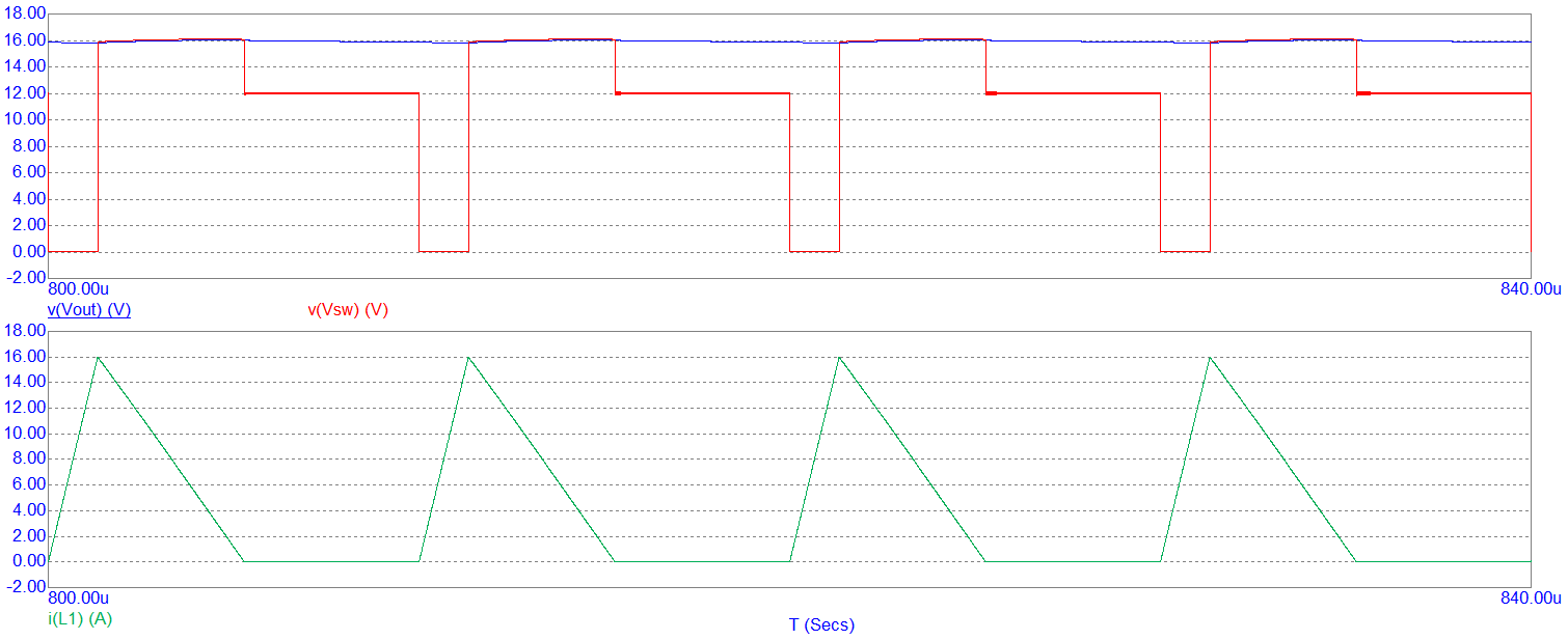
As you can see, the output voltage ($V_{O}$ in blue) hits 16 volts very nicely and, as expected, the peak inductor current ($I_{PK}$ in green) is 16 amps.
Transient analysis with non-ideal (UF5408) diode: -
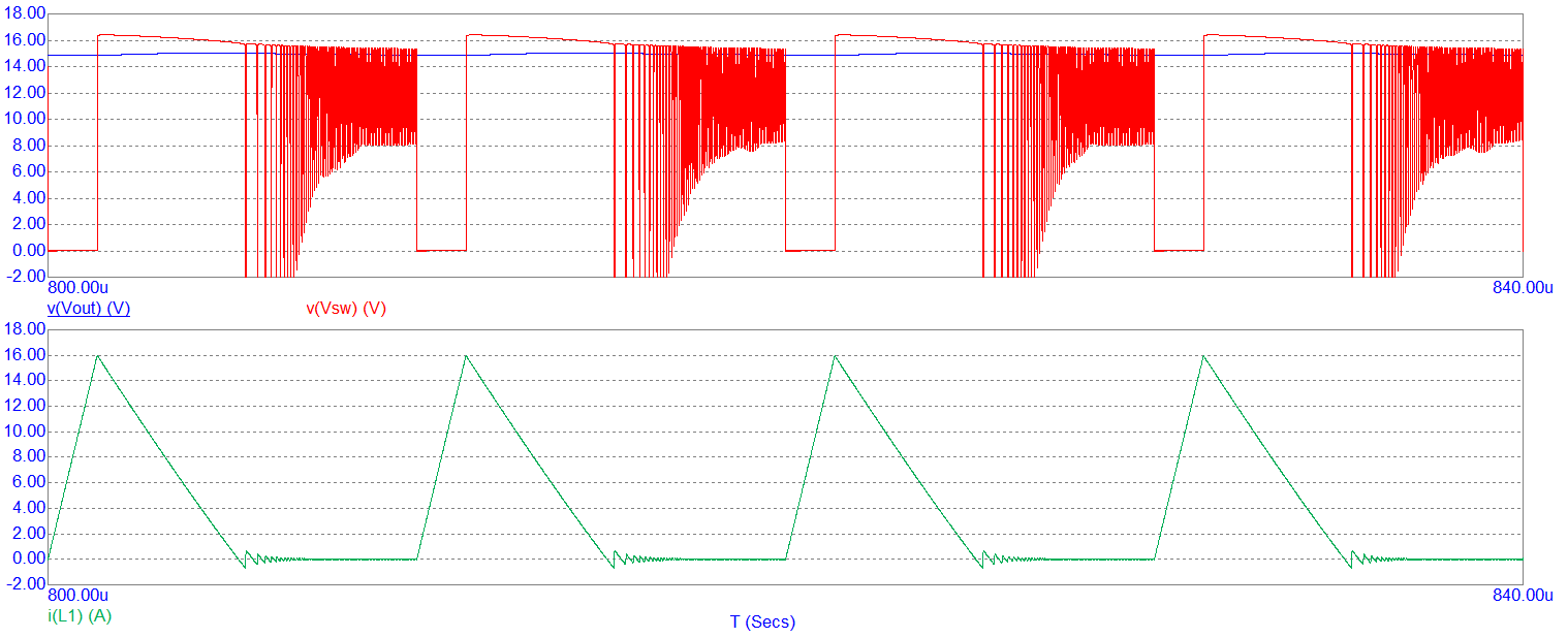
Now, the output voltage is around 15 volts due to the forward conduction diode losses. But, as I said earlier, the control-loop that monitors $V_{OUT}$ will make the necessary adjustments to D to ensure that 16 volts is produced.

0 comment threads