Control logic for mosfet in piezoelectric energy harvesting circuit
I'm working on an energy harvesting circuit known as an in-house harvesting circuit (cc-ih) and would appreciate some guidance on implementing it in Simscape within Simulink.
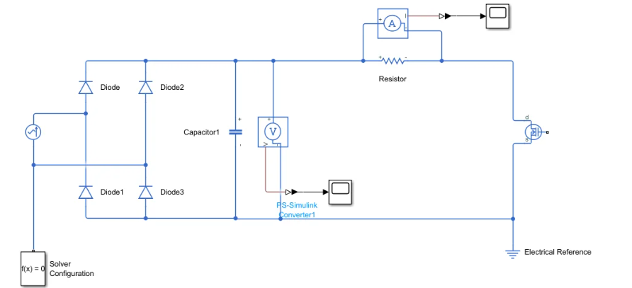
Circuit Description: The circuit is designed to harvest energy using the following key components and process:
AC Source and Rectifier: An AC voltage source feeds into a full-wave bridge rectifier consisting of four diodes. This setup converts the AC input into a DC output.
Capacitor Charging: The rectified voltage charges a capacitor, which stores the harvested energy.
Voltage Monitoring: A voltage sensor monitors the voltage across the capacitor.
Control Logic with MOSFET Switching:
The control logic monitors the capacitor voltage.
Once the voltage reaches a threshold of 2.4V, a MOSFET is triggered to connect, allowing the capacitor to discharge through a resistor (acting as a load).
The MOSFET is turned off when the voltage falls below the threshold, allowing the capacitor to recharge.
The problem i am facing is that i am stack at how to create that control logic for the MOSFET. I tried relational operatios combined with constant and logical operators and the voltage wasn't the one expected. i wasnt seeing the capacitor charging and discharging. So i wanted to ask help, if somebody could guide me what blocks to use for the control logic and how to implement it in simscape. My current implementation (the control logic is missing) is this one:
edit, supplemental information:
The origin of the circuit is in this article: Finite element-based assessment of energy harvesting in composite beams with piezoelectric transducers (2014). It's described on page 7 .
2 answers
I'll take it that you want this circuit to actually work, not just appear to work in some software simulation. In that case, it's about the circuit, not the simulator. A simulator is just one tool in designing or verifying a circuit. A brain and a calculator are usually much better tools.
First, since your AC voltage is so low, think about using Schottky diodes. That should give you an extra 700 mV or so of output for the same AC input. That's about 30% more in your case.
You might not be able to use Schottky diodes if the AC source is very high impedance or very slow, or intermittent with long off-times. In those cases the reverse leakage of Schottkys would make them worse than silicon diodes.
Your question seems to be about designing a threshold detect circuit to switch the load on and off. How "relational operatios combined with constant and logical operators" work in some simulator is the wrong question. Even if you get it working, what are you going to do? Buy a reel of relational operatios ICs to make the actual circuit?
It would help a lot to know more about this AC signal you are harvesting power from. What's its open-circuit voltage, impedance, availability, etc? Probably quiescent current is an important parameter, but you haven't told us enough to know that.
You need to design a threshold-detecting circuit that takes almost no current below the threshold. That's actually not that hard, but you have to think in terms of real parts, not what pretend-parts some simulator provides.
Once we have better parameters, we can get into a real circuit.
0 comment threads
Every real part has resistance including your piezo current source. Every switch resistance is a loss in energy (I^2 R * t)=E and includes diode and transistor switches.
What you need, I think, is to incorporate MPT theory into your block diagram and use a goal of matched impedances to achieve it. Otherwise, it won't even work in a simulator.
Try to obtain and list the following;
- Source resistance at Imin:max
- Rectifier resistance table from datasheet plots using the absolute and incremental slope of the VI curve @25'C. Use a spreadsheet if you can't find it on the web. It's the incremental resistance that you can try to match for MPT, (neglecting reactance for now)
- Capacitor values C,ESR options , Choose a few as if C is too large you won't get enough voltage Ic = C*dV/dt or have to wait too long, dt to rise dV.
- Identify all other loads and where losses can occur.
- Choose how much power and time you want to test then determine the best plan to harvest into some load.
- Estimate best and worst-case efficiency. At low currents of 100uA , you have choose parts with lowleakage resistance.
0 comment threads

0 comment threads