Comments on Design rules for opamp bootstrapping
Parent
Design rules for opamp bootstrapping
Here is the bootstrapping technique for opamps, as exposed in the Art of Electronics: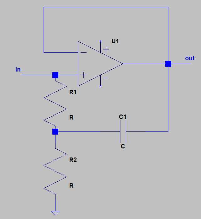
This technique is supposed to increase considerably the input impedance of the opamp for an AC input source (usually passed through a cap). The Art of Electronics considers it somewhat outdated, as it is now possible to use extremely low bias input current opamps.
I disagree with him: I see no reason to buy a somewhat expensive femtoamp opamp when you can obtain the same result with a more banal one (as long as we deal with AC sources).
Actually I do have an application where I use the self capacitance of a rotating half cylinder to measure the ambient electric field, which is perfectly tailored to bootstrapping.
Now, to make my question precise:
Assume
-
I have an AC sinusoidal source of known frequency w;
-
I want the output signal (voltage) be at least n percents of the input signal (e.g. 99%);
-
I want the RMS input current be equal to at most I_max.
Question: how should I choose the values of the two resistors and of the capacitor in the schematic above?
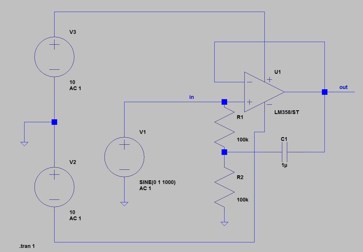
Edit: Here is a simulation done with LT spice. I've more or less given random values, following nothing but some intuitive guess:
Simulation with bootstrap:
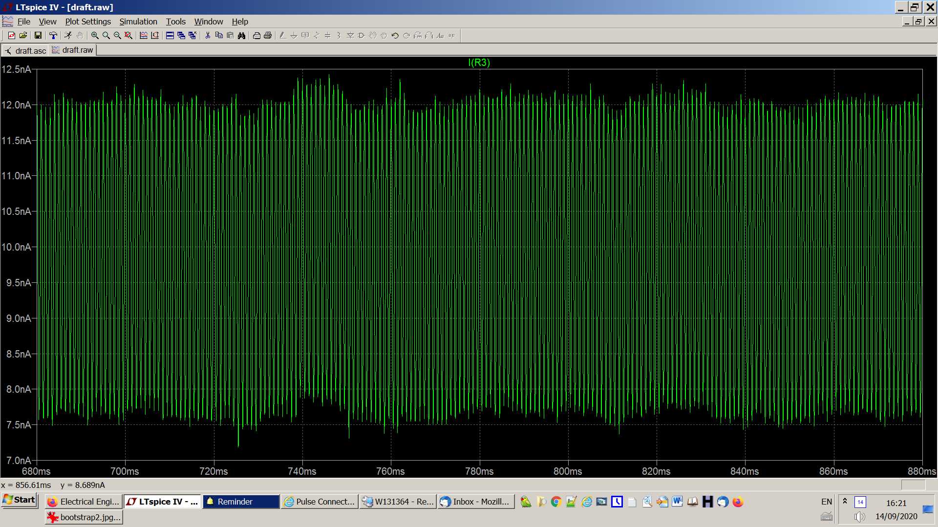
Result (current through the sine generator):
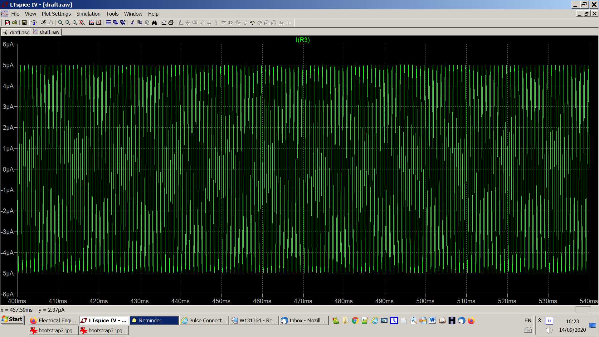
Result of the same simulation but without cap C1:
Edit 2:
Perhaps the schematic will make more sense if we pass the input signal through a capacitor, as is usually the case. Here is the schematic for the simulation:
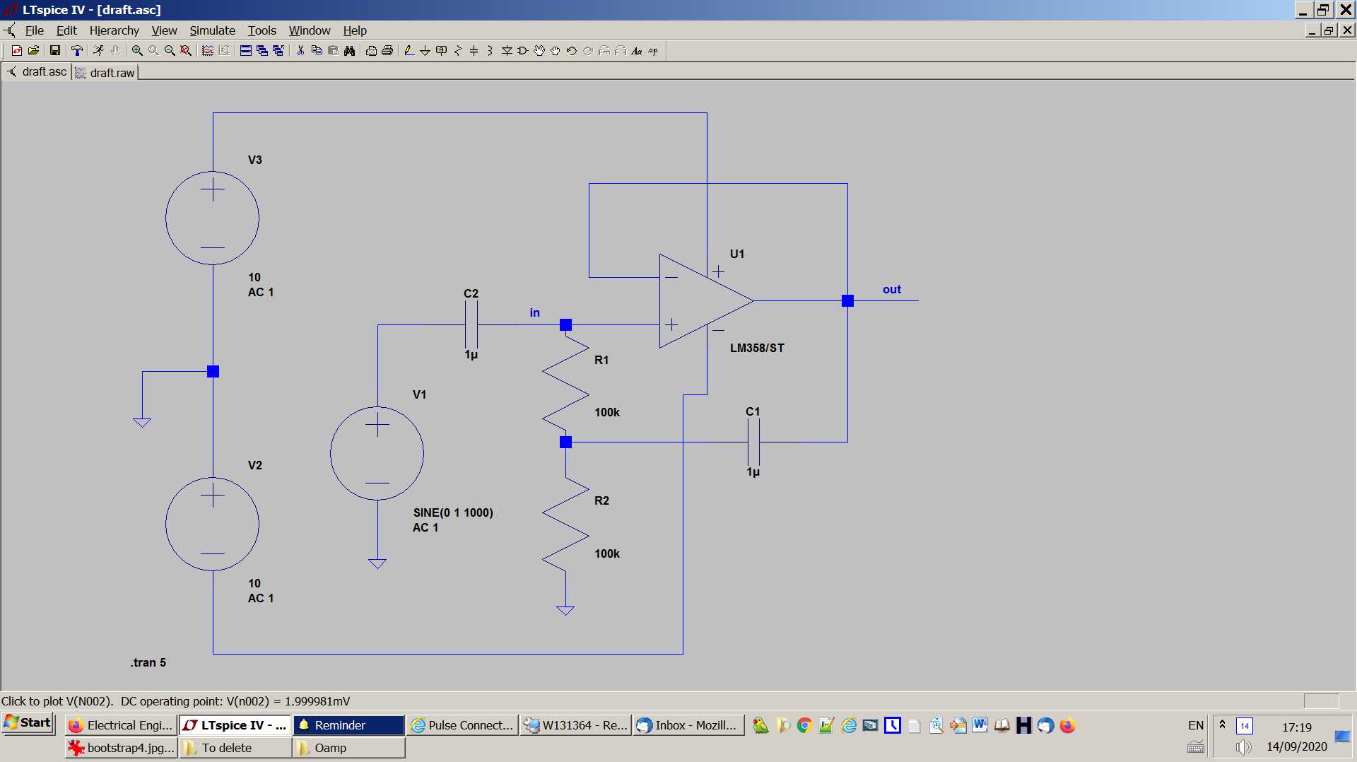
And here are the results: the first trace is the current through cap C2, and the second trace is the current at the in+ of the opamp:
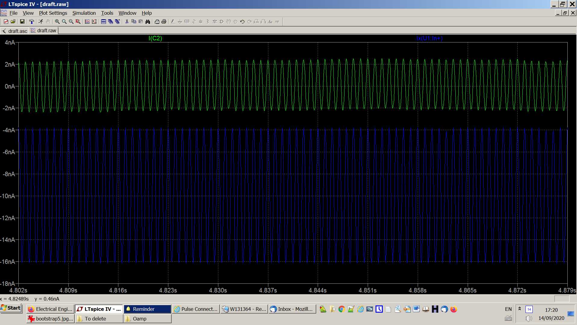
So, we see that the amplitude of the current through C2 is about 2nA, and the amplitude of the AC current at in+ is 6nA, more than I_C2.
Without cap C1, the current through the sine generator (and hence through C2) is the same as previously
Post
That circuit doesn't do what you think it does. Here is the circuit in question:
The impedance seen at IN is definitely higher at high frequencies, but that is only due to it being artificially low at DC.
At DC, there is a load of 2R on IN, in parallel with the opamp input impedance. At high frequencies, but within the opamp's range, the voltage on the left side of C1 is the same as IN. That means there is no voltage across R1, which means there is no current thru it. At high frequencies, therefore, the load on IN is only the opamp input impedance.
Put another way, the resistors add load on IN, which the circuit removes at high frequencies. However, the load due to the opamp input is always there.
A similar circuit can offset input impedance, but there has to be some positive gain from IN to OUT. Then at high enough frequencies, the left end of C1 is the same signal as IN, but a little larger. This then has the effect of adding a negative resistance load to IN. If that negative resistance exactly offsets the positive resistance of the opamp input, the net effect is apparent infinite input impedance. However, again, that requires a gain above 1 from IN to OUT. Your circuit is a voltage follower, which has a gain just under 1.
The technique above is very difficult to get right, mostly because the opamp input impedance needs to be known accurately. For example, if the opamp input impedance happens to already be 0, then trying subtract a fixed impedance from it will make things worse.
Nowadays, opamps with high input impedance are cheap and available. There is no point trying to play games like this, and the cost is minimal compared to the whole system.
You say you are trying to build a field mill. The cost of the motor and battery alone will swamp any reasonable electronics for detecting the field.
Without cap C1, the current through the sine generator (and hence through C2) is the same as previously
That means that the impedance presented to the sine generator is the same in both cases. Since the voltage is the same, and you say the current is the same, the impedance must also be the same.
However, that doesn't make much sense. At DC, the load should be R1+R2, which is 200 kΩ. There will be some load due to the opamp input, but that should be small relative to 200 kΩ.
The opamp is a voltage follower, so OUT should be driven to the sine generator output. For sufficient frequency, that will also appear on the left end of C1. That results in 0 V across R1, which means 0 current thru it, which means R1 presents infinite impedance to its top end.
This means there should have been a difference in sine generator output current with and without C1.
What is the amplitude of the sine generator output? That divided by 200 kΩ should be the current out of the sine generator with C1 removed.
I noticed that the two voltage sources for powering the opamp are labled AC1 and AC2. Those need to be DC sources.


1 comment thread