Comments on De-bouncing input signals?
Parent
De-bouncing input signals?
I've heard that input signals to digital circuits should be "de-bounced", at least sometimes. What is de-bouncing? Why is it needed? When is it needed? What is bouncing around in the first place?
Post
Another hardware solution
There is another hardware debouncing technique widely used in the past. It is implemented by an SPDT push button driving (buffered by) an RS latch.
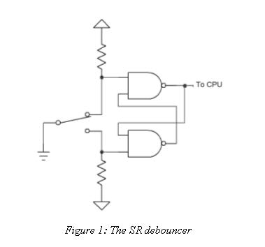
This configuration can be thought of as an "electromechanical timer 555" since it is based on the same idea - "artificially created hysteresis". Here the hysteresis is mechanical (the distance between the end contact surfaces) while in 555 it is electrical (the difference between ⅓ and ⅔ voltage levels). The same idea is implemented by the so-called "limit switches" where the hysteresis is determined by the distance between them.
In my opinion, it is the most reliable debouncing technique but it needs a more complicated switch, two pull-up resistors and an RS latch.
Mixed solution
But in these "micro times", we can implement the RS latch by the micro software so only the SPDT button will be needed… and, of course, two port inputs. The one of them will serve as an S input and the other - as an R input. Simply speaking, we remove the latch and connect the two output button terminals directly to the port. The software will write "1" in a memory cell (flag) when the S input is affected and "0" when the R input is affected.
Useful debouncing
There is such an inventive principle - use something harmful for some useful purpose. Let's try to apply it here.
The bouncing push button produces a random number of pulses; it acts as a "fading away pulse oscillator". So, if we drive a counter by a push button, it will counter a random number of pulses when pushing the button… and this arrangement will act as a random number generator.

0 comment threads