Communities

Writing
Writing
Codidact Meta
Codidact Meta
The Great Outdoors
The Great Outdoors
Photography & Video
Photography & Video
Scientific Speculation
Cooking
Cooking
Electrical Engineering
Judaism
Judaism
Languages & Linguistics
Software Development
Mathematics
Mathematics
Christianity
Christianity
Code Golf
Code Golf
Music
Music
Physics
Physics
Linux Systems
Linux Systems
Power Users
Power Users
Tabletop RPGs
Tabletop RPGs
Community Proposals
Community Proposals
tag:snake search within a tag
answers:0 unanswered questions
user:xxxx search by author id
score:0.5 posts with 0.5+ score
"snake oil" exact phrase
votes:4 posts with 4+ votes
created:<1w created < 1 week ago
post_type:xxxx type of post
Search help
Notifications
Mark all as read See all your notifications »
Q&A

Comments on Understanding the s11 and s21 coefficients of a microstrip line with resistor to ground

Post

Understanding the s11 and s21 coefficients of a microstrip line with resistor to ground

+2
−0

I thought I understood the theory of scattering parameters, smith charts etc. until I tried a practical example.

The following stupid example is supposed to be a microstrip line shunted by two 100 Ohm resistors to ground, that is, an equivalent resistance of 50 Ohm (also checked at DC with a voltmeter). microstrip 50ohm

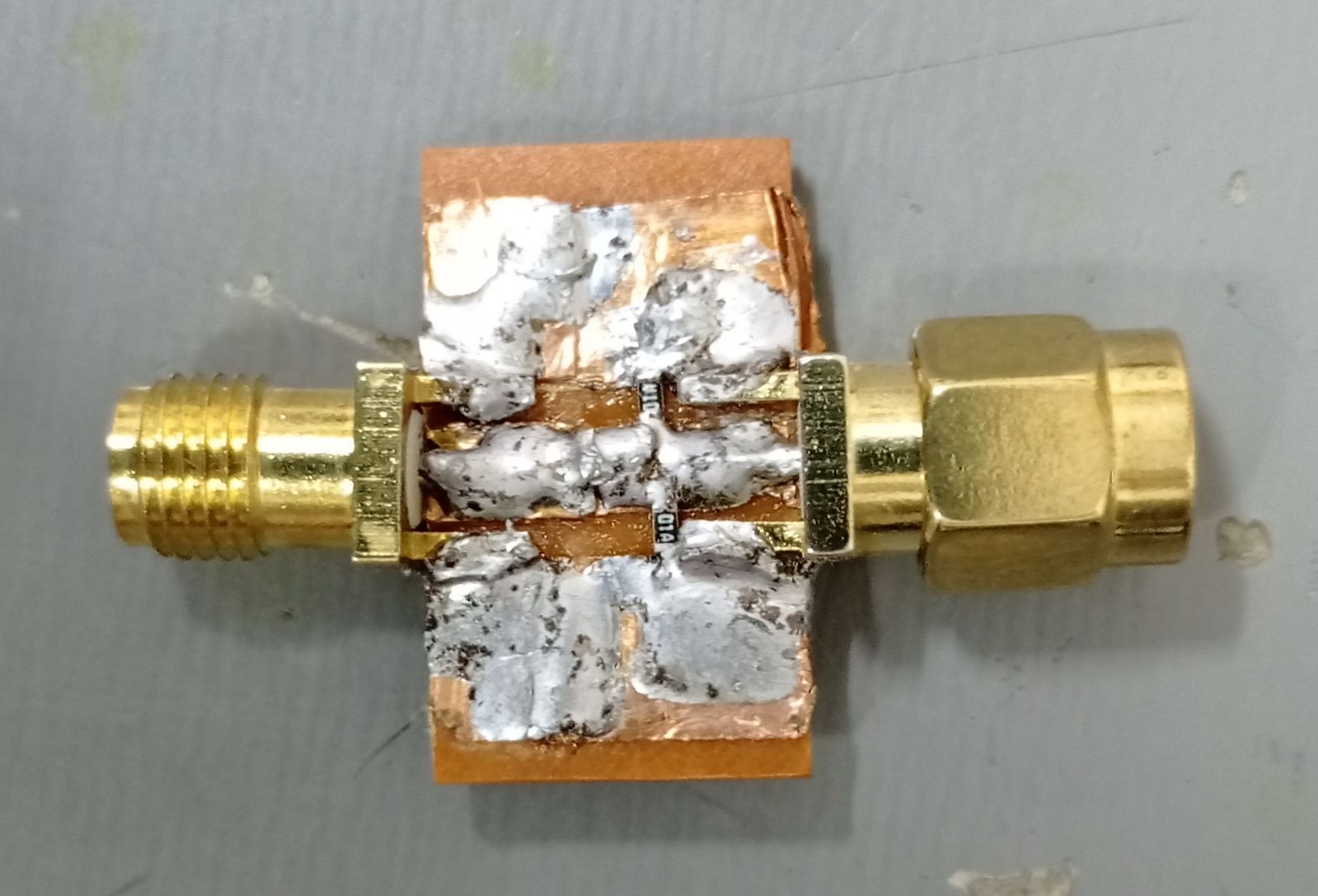
Note: the bottom of the plate is copper plated.

Now, I cannot afford a good network analyzer, so I bought a nanoVNA network analyzer (image below). Admittedly, this is a toy, but it is a well regarded toy, especially for frequencies below 300MHz. So, I assume it gives not so bad results for this experiment. nanovna

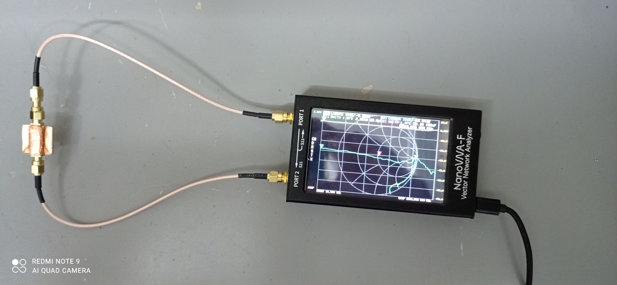
Note: the analyzer has been calibrated.

Testing the example above, here are the results returned by the nanoVNA:

vnaResults1 The yellow line is s11, approximately -9db, and the blue line is s21, approximately -3.53 db, measured and constant in the range 10kHz - 1GHz.

Now, -9 dB is equivalent to a ratio of 0.34 approximately, and -3.53 db is equivalent to a ratio of 0.66 approximately. I expected S11 to be near 0. Regarding s21, I didn't know exactly what to expect.

Notice that these measurements begin at 10 kHz, where everything should behave like the theory, due to the very low frequency.

Trying to understand these values, I finally found an excellent article, full of practical data.

Now, according to fig. 1, it seems that the stimulus has an output impedance of 50 ohm. This is my first question:

Question 1: Should we assume that network analyzers are built in such a way the stimulus (signal toward the port) has an output impedance of 50 ohm?

Question 2: How to understand the above results ?

History
Why does this post require moderator attention?
You might want to add some details to your flag.
Why should this post be closed?

1 comment thread

General comments (3 comments)
General comments
Lundin‭ wrote over 3 years ago

What's the impedance of cold solder blobs? Probably not 50 ohm... also, looks like a potential short to the left on the first pic. These are some seriously cold joints. My advise is to throw this in the garbage, then make a new attempt with larger 1210 or 2512 etc, as large as you can fit. Heat the part like there's no tomorrow and use the thickest tip you got.

Andy aka‭ wrote over 3 years ago

Q1A) We shouldn't assume anything about the network analyser that isn't documented in the manual/data sheet.

coquelicot‭ wrote over 3 years ago

@Lundin. Admittedly, the "thing" looks bad, worse than it really is, because there are reflections and other image artifacts. But I am sure there is no short. I may do a more pretty circuit and post it this week when I am in my lab. On the other hand, if you already know how the s11 and s21 SHOULD look in theory, please, just tell that in an answer.