Comments on Confused about the amplitude and shape of output voltage pulse
Parent
Confused about the amplitude and shape of output voltage pulse
In the circuit below, I am applying a $3.3Vpp$, $63kHz$, 50% Duty Cycle, PWM input signal at the gate of the mosfet and I am expecting to see a similar waveform with different amplitude at the LED cathode. (I am expecting $3.3V - V_{F,led}$ when the Mosfet is ON or $0V$ when the mosfet is OFF). According to the datasheet, the typical forward voltage of the LED is $V_{F}=1.3V$ for a forward current of around $I_{F}=10 mA$.
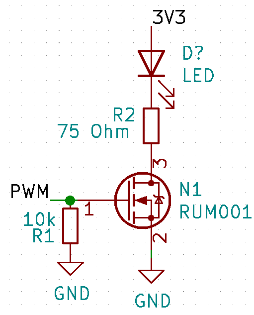
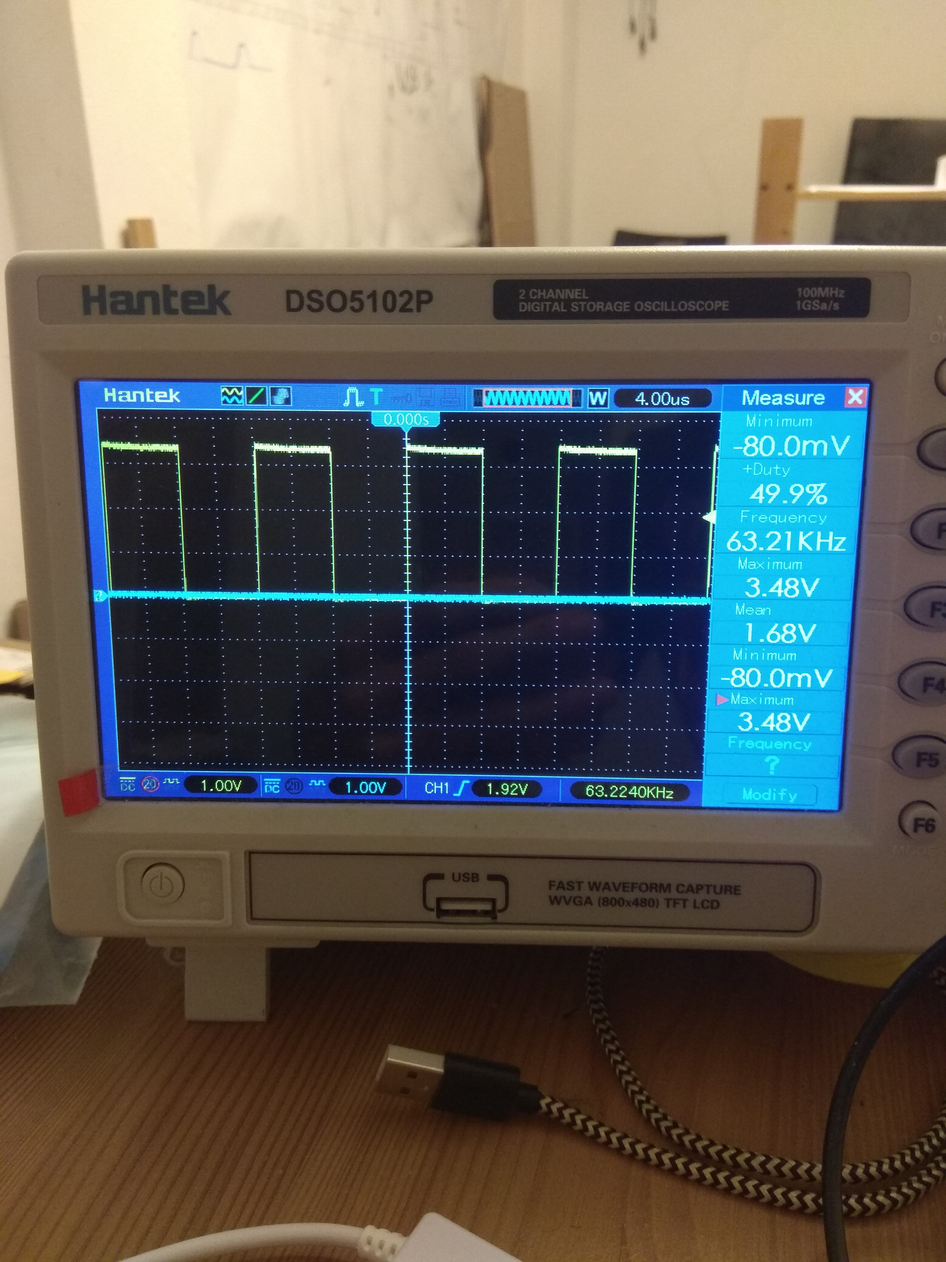
The input PWM signal as well as the voltage at the cathode of the LED (or equally the voltage across resitor $R2$ plus the Mosfet's $R_{DSon}$) are shown in the two images below as captured from the oscilloscope.
My question is three-fold:
- As you can see, when the input voltage at the gate is at $3.48 V$, the voltage at the LED's cathode is at $2.52 V$. Why isn't the voltage on the cathode of the LED in this case at $3.43 - 1.3 \approx 2.1V$? I.e, where does that extra $0.5V$ come from?
- Additionally, why is the $V_{cathode}$ at $1.36V$ and not $0V$ when the PWM input is $0V$?
- Lastly, what's the effect that causes $V_{cathode}$ to be a bit wavy and not identical in shape with the input PWM pulse?
Thank you and Merry Christmas.
Post
Coquelicot's answer explains what is going on, so I won't duplicate that.
However, one of the sources of confusion is that you are looking at the two waveforms in isolation. Your scope obviously has at least two channels, since we can see a unused blue line in each picture.
Use both channels. Set everything up like in the first screen shot, meaning to show and trigger off the input signal. Then put the probe for the second channel on the LED cathode. Now you will see both signals together. The fact that your circuit inverts will be immediately obvious.
mistake on my part, to assume the x-axes would be matched
Yes. The scope is clearly set up to trigger on a rising edge, when it crosses about 2 V. When you look at each trace separately, each signal will be shown aligned to the trigger point at a rising edge. If the signals happen to be inverted (as they are in this case), then the two signals will be shown phase shifted by 180° relative to each other when viewed separately.
When a scope shows multiple traces, they are shown together in time. You choose which signal will be used as the trigger. I suggested using the input signal as the trigger, since it's the cleaner and more obvious signal, and what is causing the other signals. When you do that, you will see the LED cathode voltage go down as the input goes up, and vice versa. This would actually be a good lesson.
Go try it, even though you may already know what you will see. Then you can crank up the time scale and see that the signals are not exactly inverted from each other. When you get to 1 µs/div or less, the delay should be apparent. It would actually be quite educational to see how exactly the LED cathode responds to the input signal at the sub-microsecond level. You will notice some asymmetry in the response too. Think about that for a bit, then come back here and ask another question if you can't figure out what is going on at the detail level.

0 comment threads