Comments on Is this AD8307 fake?
Parent
Is this AD8307 fake?
I am trying to test a AD8307. Here are my connections:
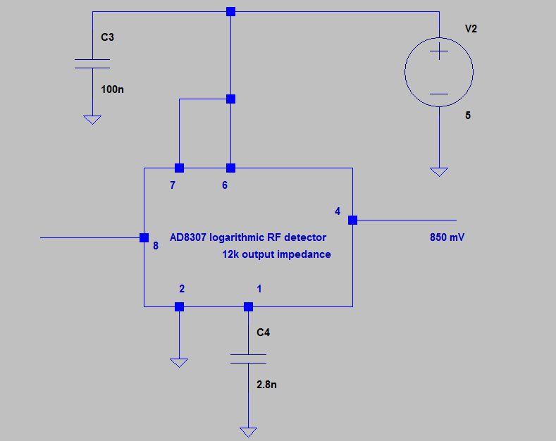
(pins not shown are left unconnected, and also pin 8).
I get a quiescent output voltage at pin 4 of about 850 mV with respect to ground, which, to my best understanding, means that the IC is fake.
What do you think?
ADDED: As I wrote, pin 8 is left unconnected. According to the datasheet, the input impedance of the IC is 1 kOhm. I am not working inside a microwave oven or near high voltage sparks, so, I can hardly imagine that the tiny pin 8 acts as an antenna or so to provide such a voltage discrepancy, but to make that sure, I tried to put it in a metal box and that made no difference.
Post
I am not familiar with that chip, and only took a very quick look at the datasheet. Here is the block diagram of the part from the top of the first page:
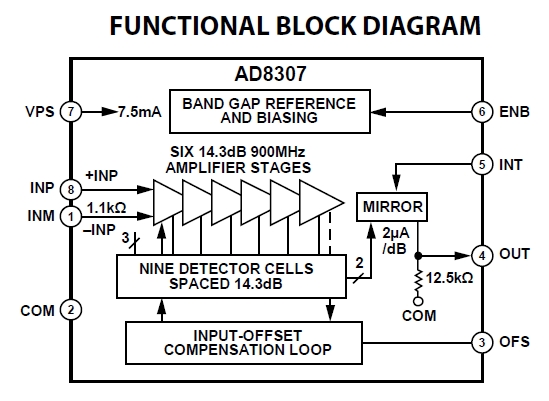
A few things pop out from this:
- This chip has a differential input on pins 8 and 1. You tied the negative input to ground via a cap, but left the positive input floating. This leaves open the possibility of the input seeing stray signals, especially considering this chip is intended to work over radio frequencies that are common all around us.
- You don't show what you have done with the INT input (pin 5), so we can only assume various strange things. This could clearly cause problems.
- You don't show what you have done with OFS (pin 3), so we can only assume various strange things. This could clearly cause problems.
- The 850 mV output is across 12.5 kΩ internally. That means 68 µA are coming out of the "MIRROR" block, which implies 34 dB input. How do you know that is incorrect, given the floating input and who knows what connected to the INT and OFS pins?
In summary, given all the strange things you're doing to this chip, we can't tell what its output should be, and can't comment on whether it is working correctly or not. You need to fix your schematic symbol then document your actual circuit properly. Maybe in the process of that you'll find a problem yourself.
Added
I skimmed the datasheet a little further and found this plot:
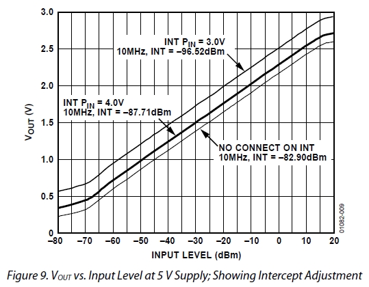
This shows that if you actually left INT open, then your output voltage indicates about -50 dBm input. How do you know you don't have that? Again, though, since we don't know what you did with the INT pin, anything is possible. I'm going to stop here because speculating further with so much missing information is likely just going to waste my time.

1 comment thread