Comments on Contactor control - Higher voltage PWM
Parent
Contactor control - Higher voltage PWM
I have a battery pack that consists of 18650 battery cells(14 cells in series max.). Hence, the voltage of the battery pack will be between 35V and 60V(to be on the safe side)
I am designing a BMS in order to control it with cell monitoring, analog measurements, contactor control, etc. features built-in.
Using the battery HV pack voltage(35-60V), I would like to control a 12V/1.5A coil of a contactor. The reason for that being the fact that the rest of the circuitry could be powered with a 5V/500mA buck converter and not having a 12V/2A supply only for the sake of contactor control would be nice.
Would the following architecture for that purpose work in real life? Is there a better way of doing this?
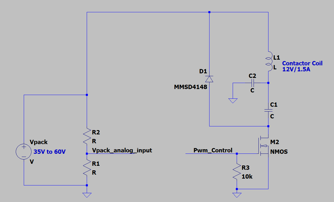
Here is how the circuit should work. Vpack_analog_input is fed into the micro analog input. The circuit around L1, C1, and D1 serves as a flipped buck converter having an NMOS instead of a PMOS. C2 is providing a low impedance for the switching node because I fear the ringing would cause a significant amount of emissions on the input cable.
The idea is to sense the Vpack and initially allow M2 to be opened for no more than t=L1*Icoil/Vpack , and after that apply PWM to Pwm_Control and limit the duty cycle in order to never have more than a certain threshold of current flowing through L1(to be done through experimenting).
Post
Your basic idea is fine, but your implementation is not. C1 makes the whole thing not work, as it will block DC. C2 puts a burden on the switch. D1 would preferably be Schottky.
I'll write a more detailed answer when I have time, probably tomorrow.
I'm back now and have more time to answer this question properly.
Again, your basic concept is fine. You can use the contactor coil as the inductor of a buck converter to keep a reasonably steady current flowing thru that coil.
With the right PWM duty cycle, the coil will act just like it is being driven with steady 12 V. It's the current thru the coil that produces the magnetic field that ultimately activates the contactor. As long as the voltage doesn't exceed any insulation breakdown limits, it doesn't really matter other than to cause the desired current. That voltage can contain AC components. Since the inductance of the coil smooths out the current, only the average applied DC voltage matters as long as the AC components have high enough frequency.
Here is the basic topology that achieves the above:
Note that there must be a DC current path thru the coil, which C1 in your schematic prevents. The PWM frequency should be high enough so that the coil current changes little during one pulse. The microcontroller producing the PWM signal is also measuring the power voltage, so it can adjust the PWM duty cycle to result in average 12 V across the coil. The accuracy requirements are not that strict, so doing this open-loop is good enough. Make sure that the micro is reading the power voltage, and therefore adjusting the PWM duty cycle, often compared to the expected changes in the supply voltage.
One possible problem with the above circuit is that the bottom node of L1 sees large and fast voltage excursions. These can possibly cause unwanted radio emissions. If the whole unit is contained in a shielded box, and you pay careful attention to grounding and the return currents, then you probably don't need to do anything more. However, if the contactor is connected to the circuit by a pair of external wires, then the voltage spikes will probably need to be filtered.
Here is a schematic snippet from a real commercial product where I needed to drive an external solenoid valve, and wanted to control the apparent drive voltage from a microcontroller:
Note the additional inductor L6 and capacitors C32 and C30. These smooth the voltage across the coil, which is at the end of an external cable connected to P19B and P19A. Instead of the rapidly-pulsing voltage being on the bottom end of the solenoid coil, it is at the bottom end of L6. L6 is on the same board as the rest of the circuit. The board has a ground plane, and the loop currents were carefully considered in layout.
You may be wondering why I bothered to do all this when the supply voltage was already the correct voltage for operating the solenoid. In this case, I wasn't trying to adjust to supply voltage variations, but wanted to be able to throttle back the solenoid drive current once its initial pull-in was completed. That was largely to reduce the heat dissipated by the solenoid in steady-state on condition, which was a problem with the previous version of this product. Solenoids are often specified for a "pull-in" drive level, with a lower "holding" drive level. This circuit allowed for switching to the holding level after the solenoid was done moving. If I remember right, I kept the PWM duty cycle at 100% for 1 second, then switched it to the holding level after that. A few 100 ms would probably have been good enough, but the amount of heating during the extra fraction of a second was inconsequential.
keep the reverse voltage in mind. 60V is too much for standard Schottky.
60 V is getting up there, but is still doable. The Vishay SS8PH9-M3/87A is one example. Fortunately, once the voltage gets so high that a Schottky isn't available, the extra voltage across a full silicon diode will be a smaller fraction of the whole.

1 comment thread