Comments on Help with differential to single ended voltage converter
Parent
Help with differential to single ended voltage converter
Hello I don't understand how this differential to single-ended voltage converter can work.
What I don't understand is why we place a current mirror(a current mirror copies the current flowing through one transistor to another transistor) and how is the output voltage affected by the input voltages.
Post
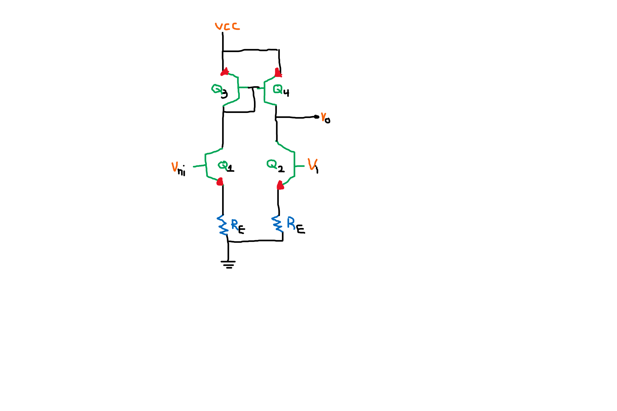
First, let's draw the schematic properly so that it's not so annoying to look at:
Yes, it's a differential amplifier. Q1 sinks current as a function of VIN+. Q3 and Q4 are a current mirror that takes the current sunk by Q1 and dumps a current of the same magnitude onto Q2. When VIN- is a little below VIN+, that is more current than Q2 can sink, so VOUT goes high. When VIN- is a little above VIN+, then the current dumped onto Q2 is less than it will try to sink, so VOUT goes low. As a result, VOUT is the highly amplified difference of (VIN+ - VIN-).
One advantage of this topology is that the gain is very high. If the collector current of a BJT were truly independent of the collector voltage, then the gain would be infinite. This would be true even if the individual transistor gains were finite.
Another way to think about this is that Q4 is a current source driven by VIN+ and Q2 is a current sink driven by VIN-. When two ideal current sources are connected together like that, the result is either clipped high or clipped low whenever the two aren't exactly equal. The only reason VOUT will have any intermediate voltages is because the two current sources aren't ideal.
Some disadvantages of this topology:
- The loading on VIN- depends on VIN+. When Q2 is not saturated, R2 is reflected onto VIN- times the gain+1 of Q2. When Q2 is saturated, then the dynamic impedance seen at VIN- is only R2 directly.
- The internal currents depend on the common mode voltage. This is usually undesirable when common mode rejection is important. The drive capability of VOUT is also proportional to the overall internal current level.
- The low side of the VOUT range is limited by VIN-.
I have done some experiments on falstad and every time Vin+ becomes less than Vin- Q2 is driven to saturation and if Vin+ becomes more than Vin- Q4 is driven to saturation. Is that normal?
Yes, as should have been clear from the discussion above, particularly the third paragraph below the schematic: "the result is either clipped high or clipped low".
Quote:"When VIN- is a little below VIN+, that is more current than Q2 can sink, so VOUT goes high". Of course, I agree - however, what is the clear explanation? WHY goes Vout high? We have two (non-ideal) current sources with a conflicting behaviour. How and why does this fact influence the voltage at the common point?
This discussion is getting deeper and deeper into issues not originally asked. At some point, we have to assume basic electronics knowledge outside of what was specifically asked about. You can keep asking "why" questions indefinitely. "Why is grass green?" "Then why is chlorophil green?" "What makes it look green to us?" ...
However, I'll answer this one question this time. Consider the two current sources connected in series:

Both current sources are essentially controlled pass elements. They can't actively source current, only control how much current they let thru. For simplicity, let's also say their compliance range goes from 0 V to at least V+.
Now consider what happens when I1 is set to 2 mA and I2 to 1 mA. No matter how much current I1 tries to let pass, only 1 mA will flow because that's all that I2 allows. I1 will therefore turn its pass element fully on (act as a dead short). Vout therefore goes to V+. I2 is fine with that, and will continue to pass 1 mA.
The same applies the other way around when the current source values are flipped. If I2 is trying to let 2 mA pass, but I1 only allows 1 mA, I2 will turn its pass element fully on, and Vout goes to 0.
In the general case, Vout goes fully high whenever I1 is set to more current than I2. Vout goes fully low whenever I1 is set to less current that I2.
If you had two knobs that could adjust the values of I1 and I2, then the circuit becomes a comparator. Vout is V+ when I1 > I2. Vout is 0 when I1 < I2. I1 = I2 is a mathematical curiosity only, since no two signals are truly equal in the real world, and of course perfectly ideal current sources don't exist either.
The circuit works only for non-ideal current sources. There is no other way to solve the conflict with two current sources in series.
What I showed works fine for ideal current sources as long as they are passive. They can't supply any power on their own. They can only allow a certain current to pass, as noted.
1 comment thread

0 comment threads