Communities

Writing
Writing
Codidact Meta
Codidact Meta
The Great Outdoors
The Great Outdoors
Photography & Video
Photography & Video
Scientific Speculation
Cooking
Cooking
Electrical Engineering
Judaism
Judaism
Languages & Linguistics
Software Development
Mathematics
Mathematics
Christianity
Christianity
Code Golf
Code Golf
Music
Music
Physics
Physics
Linux Systems
Linux Systems
Power Users
Power Users
Tabletop RPGs
Tabletop RPGs
Community Proposals
Community Proposals
tag:snake search within a tag
answers:0 unanswered questions
user:xxxx search by author id
score:0.5 posts with 0.5+ score
"snake oil" exact phrase
votes:4 posts with 4+ votes
created:<1w created < 1 week ago
post_type:xxxx type of post
Search help
Notifications
Mark all as read See all your notifications »
Q&A

Comments on Critically damped oscillation issue

Parent

Critically damped oscillation issue

+1
−2

I have a question about this circuit:(critically damped oscillation)

SeeMe

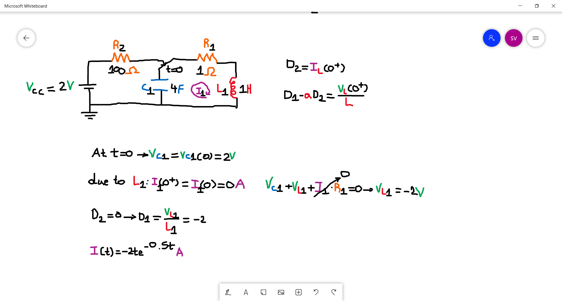
For a critically damped oscillation for a series RLC circuit the equation of current has this form I(t)=D1te^(-at)+D2e^(-at) where D2 =I(0+) and D1-aD2 = dI(0+)/dt=VL/L.

Due to L1 :I(0)=I(0+)=0A and by applying KVL in VL1=-VC1=-2V

And by substituting the values we get D1=-2A/s and D2 = 0A and we end up with an equation of I(t)=-2te^(-0.5t) but this cant be correct.What am I doing wrong?

History
Why does this post require moderator attention?
You might want to add some details to your flag.
Why should this post be closed?

1 comment thread

Close reason (3 comments)
Post
+2
−0

Your derivation is correct, you just missed the sign: $V_L=-V_C=2;\mathrm{V}$, because the capacitor charges with +2 V, and the discharge accounts for the negative sign on the inductor. The notation of $V_L=-V_C$ may be confusing, so think of it as $V_C=-V_L$, maybe it makes more sense.

Verifying your results is never a bad idea, so here it is:

test

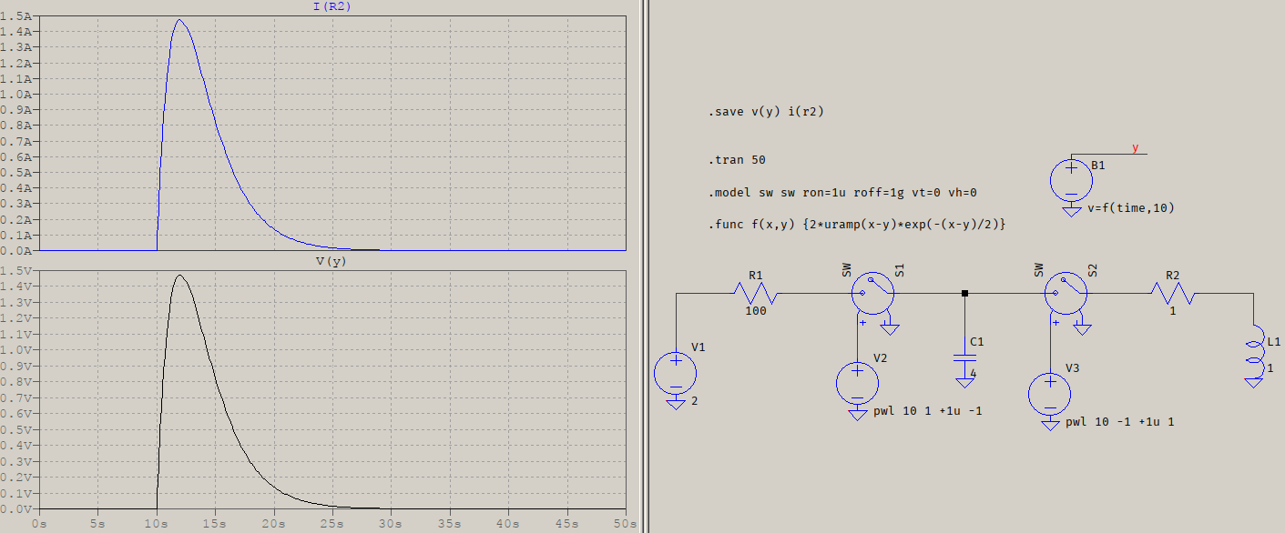
I(R2) is plotted in blue while in black it's the test voltage, modelled as a function with the same format as your result, except for taking care of the delays (the uramp() part, such that it's zero until the event).

History
Why does this post require moderator attention?
You might want to add some details to your flag.

1 comment thread

I still dont get it VL=-VC = -2V. (5 comments)
I still dont get it VL=-VC = -2V.
MissMulan‭ wrote almost 3 years ago

I still dont get it VL=-VC = -2V.

a concerned citizen‭ wrote almost 3 years ago

MissMulan‭ Draw an imaginary vertical line separating C1 from R2+L1. Now the voltage on the capacitor is mirrored to the inductor and the resistor. Since the resistor is not a reactive element, the whole initial condition applies now to the inductor, only, therefore D ends up with 2, not -2.

MissMulan‭ wrote almost 3 years ago

Sorry what you write doesnt make any sense to me.From KVL Vs=Vc+Vl+IR , I=0 and Vs=0 (no battery connected to the circuit)->VC=-VL->VL=-2V.

a concerned citizen‭ wrote almost 3 years ago

MissMulan‭ After the switch changes state, the only mesh you have is made of C, R, and L, with C precharged. Therefore there is no Vs, only Vc=Vr+VL, because Vc takes the role of Vs. With Vr=0, all that remains is VL.

MissMulan‭ wrote almost 3 years ago

Thanks I understand now/