Comments on Help with differential to single ended voltage converter
Parent
Help with differential to single ended voltage converter
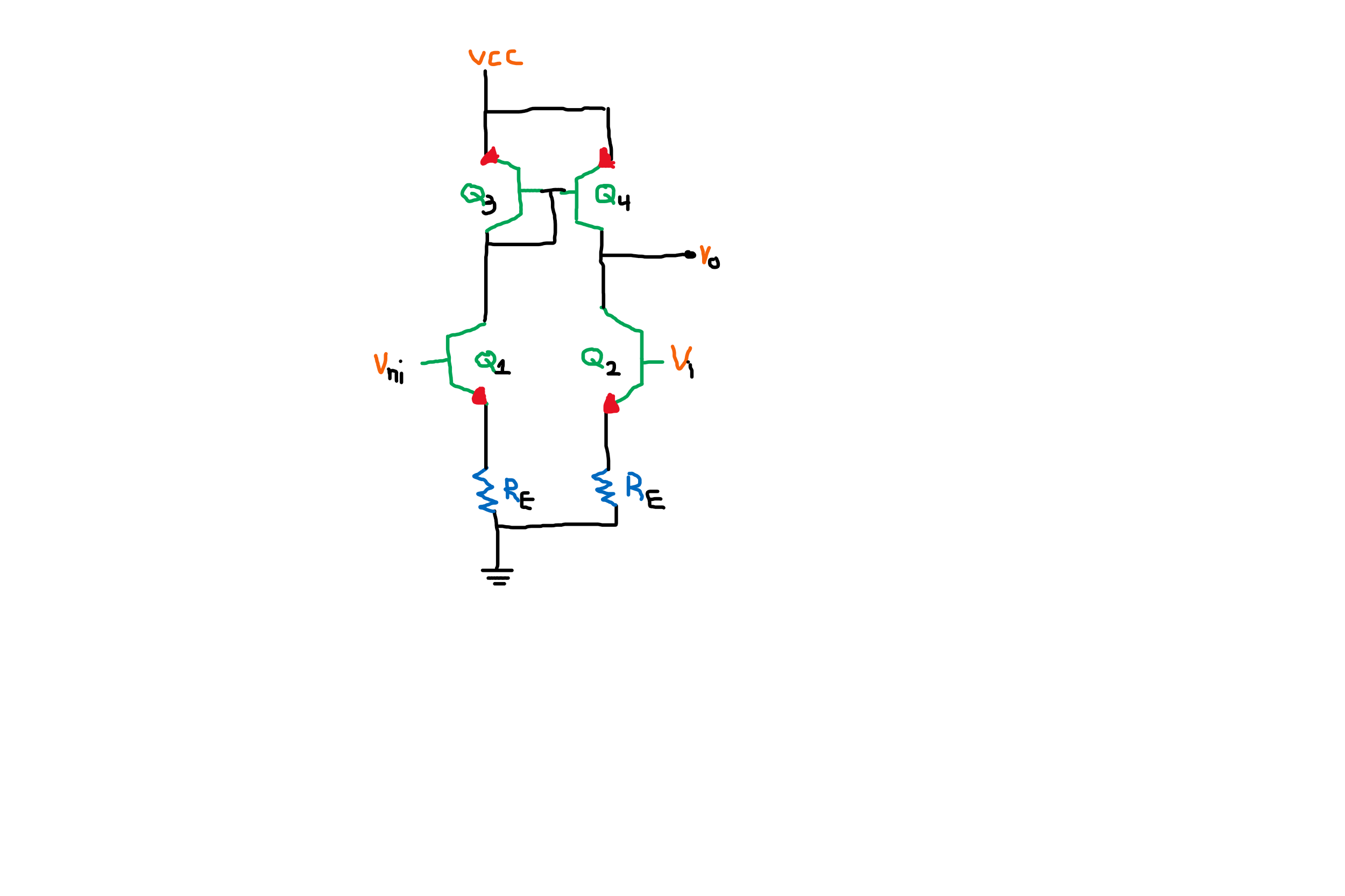
Hello I don't understand how this differential to single-ended voltage converter can work.
What I don't understand is why we place a current mirror(a current mirror copies the current flowing through one transistor to another transistor) and how is the output voltage affected by the input voltages.
Post
My Comment
I will begin my answer by commenting on the other two answers from two months ago. I will show that they do not contradict but rather complement each other.
Ideal current sources. I can not agree with Olin Lathrop's assertion that this arrangement "works fine for ideal current sources as long as they are passive" since, as he himself has noted, the circuit will be a comparator and the output voltage will stay close to one of the supply rails.
Non-ideal current source(s). "To work fine" (to be linear) in the case of the open circuit (no load connected), at least one of the current sources must be non-ideal. So, the problem is how to make an ideal current source non-ideal. There are two ways proposed since the 19th century by Thevenin and Norton.
According to Thevenin. By its nature, an ideal current source consists of a voltage source and an infinite differential resistance in series. ("differential" means that it is infinite only for current changes). To make it non-ideal, we have to decrease its resistance (make it finite). In the transistor implementation of this idea (dynamic load), the resistance is decreased because of the Early effect.
According to Norton. But what do we do if we cannot change the internal resistance of the ideal current source? How do we make it non-ideal? Norton's idea can help us.
Intentional "worsening". For this purpose, we can connect a constant (ohmic) resistor in parallel to the ideal current source. It will divert a part of the current and the combination of the two elements will act as a real (non-ideal) current source.
Natural "worsening". In fact, as LvW has noted, such resistance always exists; it is the input resistance of the next stage.
So, this arrangement will work in both situations - Thevenin real current sources without load (open circuit) and ideal current sources with load.
Both explanations are correct but Olin's explanation will be true only in the case of real current sources while LvW's explanation will be valid in both cases (real and ideal current sources).
My Explanation
We can see two clever ideas in this circuit solution that can be figuratively named dynamic load and transistor cloning. Let's try to explain them in an intuitive way.
Dynamic load
LvW: "WHY goes Vout high? We have two (non-ideal) current sources with a conflicting behaviour. How and why does this fact influence the voltage at the common point?"
Current source. Exactly, LvW! This is the main question to be answered herе! Unfortunately, this cannot be done with the concept of current source and through this circuit of two current sources in series because it is not clear what is inside these current sources and how they function. The answer to this question can only be given through the concept of dynamic resistance. What is it?
Dynamic resistor. The two "current sources" in series actually are resistors… a special kind of resistors but still resistors. In contrast to ordinary ohmic resistors, their resistance does not stay constant but varies when the current tries to change. For example, if the voltage across such a dynamic resistor increases, it increases its resistance with the same rate of change and the ratio V/R = I stays constant. In addition, this property is controlled by an input voltage.
So, the full descriptive name of these elements (implemented by transistors here) can be "voltage-controlled current-stabilizing nonlinear resistors".
Voltage divider. Two resistors in series form the well-known 19th century voltage divider. If we keep the whole voltage across the network constant, and vary some of the resistances, the voltage drops across them will vary and we can take some of them (usually, the grounded one) as an output.
Potentiometer. If, in a variable voltage divider (the so-called potentiometer), both partial resistances r1 and r2 vary in opposite directions with the same rate, their sum will stay constant. As a result, the current I = V/(r1 + r2) is also constant; only the partial voltage drops across the resistances vary (crossfade) in opposite directions.
Dynamic voltage divider. Now imagine that there is some increasing gear on the wiper and it is enough to move it slightly and the voltage changes a lot. Here, this is a simple electrical analogy of our arrangement known as "dynamic load".
Dynamic load. So, the two transistors Q2 and Q4 act as voltage-controlled dynamic resistors that, under control of two oppositely (differentially) changing input voltages V- and V+, vigorously change their collector-emitter static resistances in opposite directions (they act as two crossfading dynamic resistances). As a result, their collector-emitter voltage drops vigorously redistribute (crossfade). The whole network acts as a kind of a super sensitive electronic potentiometer (high gain amplifier). Note (LvW) that no load is required for the circuit to operate in linear mode; it can operate on an open circuit.
CMOS stage is another excellent implementation of this idea.
Transistor cloning
The network of two dynamic resistors is stretched between the supply rails so one of them is "pulling up" and the other is "pulling down". The voltage drop across the pull-down resistor is taken as a grounded output voltage.
The one input voltage VIN- is grounded and applied between the base of the pull-down "resistor" Q2 and ground. The problem is with the second input voltage VIN+ that is also grounded but, to control the pull-up "resistor" Q4, it should be applied between its base and Vcc… but this is impossible. That is why a clever trick is used which I call "transistor cloning".
VIN+ controls another grounded pull-down transistor Q1. Then, with the help of the current mirror, Q1 is cloned by Q4… as though, Q1 is moved above Q2.
From another viewpoint, the current mirror can be considered as an "electric transmission" that connects Q1 and Q2 to make the dynamic voltage divider.

0 comment threads