Comments on Series RLC circuit
Parent
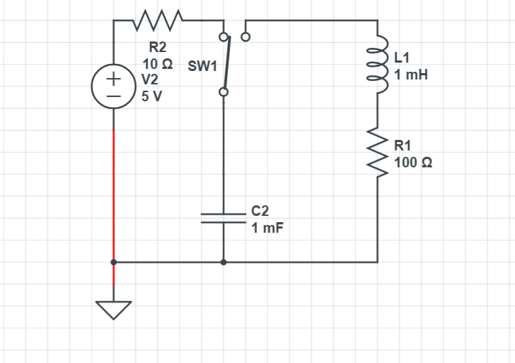
Series RLC circuit
How to find the equation of current of the RLC circuit after the switch is moved?
Post
It all depends on the values of the components:If

the system will very slowly decay until the energy of the system reaches 0.
If

the system undergoes something which will look like a part of a oscillation and loses its energy very quickly
If

it oscillates with decreasing amplitude until its energy reaches 0.
In our case:

it will very slowly decay without any oscillation.In order to find the equation of current of this RLC circuit we must be introduced to 2 things:
Neper angular frequency -> a feature of damped systems
In the case of the series RLC circuit it is:

The natural angular frequency -> the frequency response of the system under no damping
In a RLC circuit it is equal to:

The equation of current of this overdamped system takes this form:
where :

and:

Now lets go calculate s1 and s2:
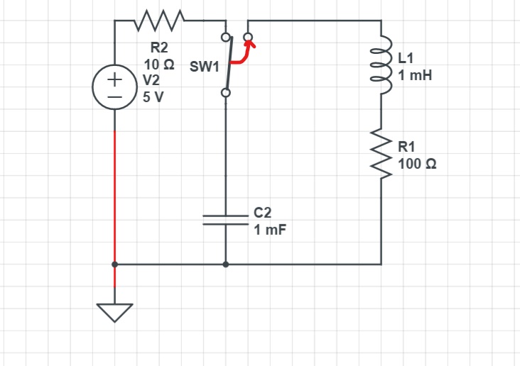
After the switch is closed:
and due to L1:
so the voltage between L1 is:

By substituting the values of s1,s2 VL1(0+),L1 and IL1(0+) to (1) and solving the system we get:

This is the equation of the current of the loop consisting of C1,L1,R1 after the switch is closed.
1 comment thread

0 comment threads