Communities

Writing
Writing
Codidact Meta
Codidact Meta
The Great Outdoors
The Great Outdoors
Photography & Video
Photography & Video
Scientific Speculation
Cooking
Cooking
Electrical Engineering
Judaism
Judaism
Languages & Linguistics
Software Development
Mathematics
Mathematics
Christianity
Christianity
Code Golf
Code Golf
Music
Music
Physics
Physics
Linux Systems
Linux Systems
Power Users
Power Users
Tabletop RPGs
Tabletop RPGs
Community Proposals
Community Proposals
tag:snake search within a tag
answers:0 unanswered questions
user:xxxx search by author id
score:0.5 posts with 0.5+ score
"snake oil" exact phrase
votes:4 posts with 4+ votes
created:<1w created < 1 week ago
post_type:xxxx type of post
Search help
Notifications
Mark all as read See all your notifications »
Q&A

Comments on Humming noise from a boost converter's inductor

Post

Humming noise from a boost converter's inductor

+1
−0

My step-up converter makes audible noise both with and without a load.I am almost certain it is the inductor, because when I hold my finger on it I can feel vibration and it gets quieter. Unfortunately, I do not own an oscilloscope and cannot inspect what is going wrong. Here is the schematic: Image alt text

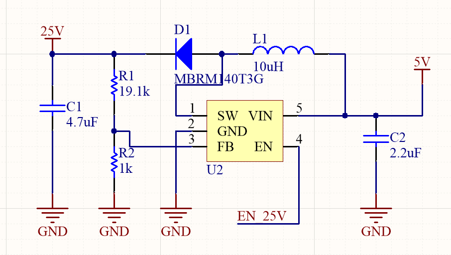
All the capacitors are ceramic, inductor is FXL0530-100-M, and the converter datasheet can be found here . On page 14, FIGURE 6-8 the recommended values are shown. Only thing I have changed are resistor values to match my output voltage, but this is a minor change. I read about audible issues with converters, and one of the points mentioned was that picking an IC with a higher switching frequency can help, but this particular one is at 1MHz, well above the one mentioned in the article I read.

What could be the reasons for this humming noise, and how could they be mitigated?

History
Why does this post require moderator attention?
You might want to add some details to your flag.
Why should this post be closed?

1 comment thread

General comments (2 comments)
General comments
Lundin‭ wrote almost 4 years ago

You really should draw these from left to right. That is left=input voltage, right=output voltage. As done in every existing datasheet for switch regulators out there.

Olin Lathrop‭ wrote almost 4 years ago

What Lundin said, since we can't upvote comments here.