Communities

Writing
Writing
Codidact Meta
Codidact Meta
The Great Outdoors
The Great Outdoors
Photography & Video
Photography & Video
Scientific Speculation
Cooking
Cooking
Electrical Engineering
Judaism
Judaism
Languages & Linguistics
Software Development
Mathematics
Mathematics
Christianity
Christianity
Code Golf
Code Golf
Music
Music
Physics
Physics
Linux Systems
Linux Systems
Power Users
Power Users
Tabletop RPGs
Tabletop RPGs
Community Proposals
Community Proposals
tag:snake search within a tag
answers:0 unanswered questions
user:xxxx search by author id
score:0.5 posts with 0.5+ score
"snake oil" exact phrase
votes:4 posts with 4+ votes
created:<1w created < 1 week ago
post_type:xxxx type of post
Search help
Notifications
Mark all as read See all your notifications »
Q&A

Comments on Flyback converter design

Parent

Flyback converter design

+3
−0

Hi guys,I'm designing a multiple output flyback converter with 2 outputs at 10v@1 Amp and 5v @ 2 Amps .Input is 20 V dc

Im having some problem with the implementation of closed loop. Open loop response comes out fine but i dont know how to control two outputs with a single control loop.

Any help would be much appreciated. Im using Spice simulation(ltspice) and matlab simulink.

If anyone have some simulation files or schematics , it would be immensely helpful.

Thank you

History
Why does this post require moderator attention?
You might want to add some details to your flag.
Why should this post be closed?

0 comment threads

Post
+4
−0

Try searching for "multiple outputs flyback". Basically, you can't control each, individually, instead you make the voltage feedback as the average between the outputs. Here's a quick'n'dirty test to show what I mean, with a simple voltage mode concoction (don't give it too much thought for the values, they work enough for this example):

2 outputs flyback test

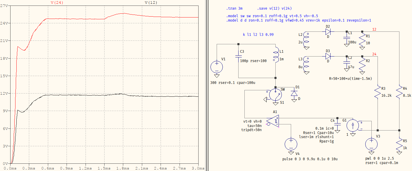
R3, R4, and R5 form a combined resistive divider which make the averaged value of the outputs appear at their junction. This is the one that the loop considers to follow. The disadvantage is that whatever perturbation exists on one output, only, will affect the other(s), too: R2 is the load for the 24 V (give or take) jumps from 50 Ω to 150 Ω, and you can see how the 12 V output drops a little. It's still stabilized, but it's the average of the outputs that is monitored, not any output in particular.

History
Why does this post require moderator attention?
You might want to add some details to your flag.

1 comment thread

simulation files (3 comments)
simulation files
Sriram14‭ wrote over 2 years ago

If anyone have a spice or matlab simul file of closed loop flyback it would help me to design my ckt alot

thank you

a concerned citizen‭ wrote over 2 years ago

Sriram14‭ The picture above is made with LTspice. It should be easy to replicate.

Sriram14‭ wrote over 2 years ago

i tried to duplicate it but the control loop part is a little difficult to recreate . if you can send the file it would help me a lot

thank you

my mail masriram14@gmail.com