Comments on How do PLCs normally measure 4-20mA current loops?
Parent
How do PLCs normally measure 4-20mA current loops?
I'm looking for input from anyone with insight in the PLC world. How do PLCs usually measure 4-20mA current loops?
I would assume it's one of these two alternatives:
- Through an external "shunt" resistor
- Through internal current sense electronics
My scenario is an industrial system where I'm looking to generate different fixed current levels in a 4-20mA current loop based on relays. The fixed current will increase depending on how many relays that are active, such as no relays = 4mA, first relay = 8mA, first 2 relays = 12mA and so on.
The circuit will either look like this:
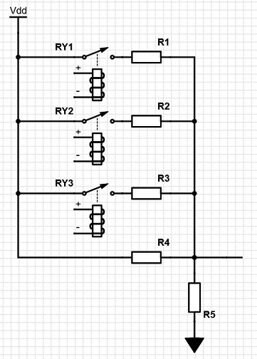
That is: current is measured across a "shunt" resistor of typically 250R added externally.
Or alternatively:
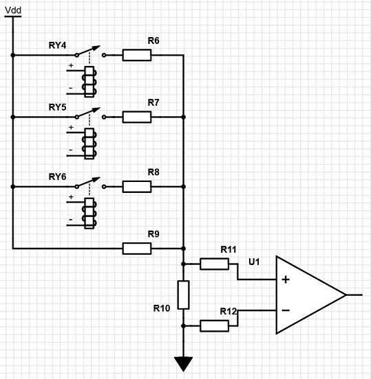
That is: R10 has very low resistance and some manner of current sense electronics are built-in inside the PLC.
In case the PLC uses the former "shunt" resistor method, then I will have to adapt my resistor values accordingly. But in case they measure over some internal low ohm resistor like in the second picture, then I don't need to consider that.
I'm looking to create a solution that will suit most PLC solutions out there, but I don't know which one of these two circuits that are the most common.
Post
You should not be relying on the internal circuitry of whatever senses the 4-20 mA current. Note that the two implementations you show both use current sense resistors. The only difference is their value.
I have designed several current-sense front ends, although none were inside a PLC. The customer gets a spec for accuracy and maximum voltage drop. I would have been reluctant in some cases to provide any further specs because that would have limited future options. The maximum voltage drop is all that the customer should care about. How I might use that voltage range isn't anyone else's business.
For example, I used a 220 Ω resistor in one case where the voltage was fed directly into the A/D of a microcontroller running on 5 V. The next iteration might have used a 3.3 V micro, or a separate A/D for higher resolution or accuracy. Someone who relied on an unspecified value, like 220 Ω input resistance, would have had trouble with the new version, even though the new version is fully backwards compatible with the previous according to all published specs.
The answer to your question is "Don't do it that way". This is clearly an X-Y problem since you are asking about an imagined solution instead of describing the actual problem.
Pop up a few levels and describe the real problem in a separate question. It seems you have a set of signals, and you want a PLC to determine how many of them are asserted at any one time. Tell us more about these signals, their voltage levels, AC/DC, whether isolation is really required, how much current they can support, etc. There are several options that come to mind, but I don't want to guess at answers that would not meet criteria that are not yet stated.
My "actual" problem is that I've delivered a 24V relay system and the customer changed their mind and wishes to have a PLC with 4-20mA inputs instead
That's definitely better than what you asked originally. Apparently you're stuck with relay outputs, and a PLC needs to be able to read the number of asserted relays via a 4-20 mA input. If that's correct, ask that as a separate question. I can think of some possibilities that don't rely on how exactly the PLC implements current measurement.

0 comment threads