Communities

Writing
Writing
Codidact Meta
Codidact Meta
The Great Outdoors
The Great Outdoors
Photography & Video
Photography & Video
Scientific Speculation
Cooking
Cooking
Electrical Engineering
Judaism
Judaism
Languages & Linguistics
Software Development
Mathematics
Mathematics
Christianity
Christianity
Code Golf
Code Golf
Music
Music
Physics
Physics
Linux Systems
Linux Systems
Power Users
Power Users
Tabletop RPGs
Tabletop RPGs
Community Proposals
Community Proposals
tag:snake search within a tag
answers:0 unanswered questions
user:xxxx search by author id
score:0.5 posts with 0.5+ score
"snake oil" exact phrase
votes:4 posts with 4+ votes
created:<1w created < 1 week ago
post_type:xxxx type of post
Search help
Notifications
Mark all as read See all your notifications »
Q&A

Comments on How do PLCs normally measure 4-20mA current loops?

Parent

How do PLCs normally measure 4-20mA current loops?

+5
−1

I'm looking for input from anyone with insight in the PLC world. How do PLCs usually measure 4-20mA current loops?

I would assume it's one of these two alternatives:

  • Through an external "shunt" resistor
  • Through internal current sense electronics

My scenario is an industrial system where I'm looking to generate different fixed current levels in a 4-20mA current loop based on relays. The fixed current will increase depending on how many relays that are active, such as no relays = 4mA, first relay = 8mA, first 2 relays = 12mA and so on.

The circuit will either look like this:

shunt_resistor

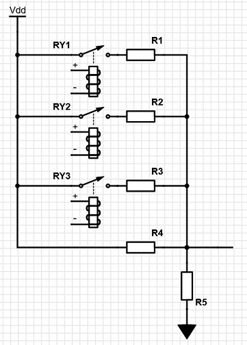
That is: current is measured across a "shunt" resistor of typically 250R added externally.


Or alternatively:

current_sense

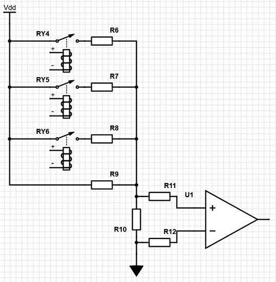
That is: R10 has very low resistance and some manner of current sense electronics are built-in inside the PLC.


In case the PLC uses the former "shunt" resistor method, then I will have to adapt my resistor values accordingly. But in case they measure over some internal low ohm resistor like in the second picture, then I don't need to consider that.

I'm looking to create a solution that will suit most PLC solutions out there, but I don't know which one of these two circuits that are the most common.

History
Why does this post require moderator attention?
You might want to add some details to your flag.
Why should this post be closed?

0 comment threads

Post
+0
−0

you want a current source start with a linear regulkator like LM340 and use the relays to switch in different load resistors.

History
Why does this post require moderator attention?
You might want to add some details to your flag.

1 comment thread

Sure but that doesn't answer the question (1 comment)
Sure but that doesn't answer the question
Lundin‭ wrote almost 2 years ago

Indeed this doesn't really give a proper current loop unless Vdd is a current generator. But I had already delivered the system when the customer changed their mind completely. So we ended up doing a quick & dirty solution just converting voltage to current over a resistor, since the PLC was located close, in the same cabinet as the relays. Now as it happened there was also some external circuits that needed to be connected, so it had to be tweaked further and it all turned into a strange "ad hoc" solution. The customer is always right, they say... and they got it running fine now though, since a few months back.