Communities

Writing
Writing
Codidact Meta
Codidact Meta
The Great Outdoors
The Great Outdoors
Photography & Video
Photography & Video
Scientific Speculation
Cooking
Cooking
Electrical Engineering
Judaism
Judaism
Languages & Linguistics
Software Development
Mathematics
Mathematics
Christianity
Christianity
Code Golf
Code Golf
Music
Music
Physics
Physics
Linux Systems
Linux Systems
Power Users
Power Users
Tabletop RPGs
Tabletop RPGs
Community Proposals
Community Proposals
tag:snake search within a tag
answers:0 unanswered questions
user:xxxx search by author id
score:0.5 posts with 0.5+ score
"snake oil" exact phrase
votes:4 posts with 4+ votes
created:<1w created < 1 week ago
post_type:xxxx type of post
Search help
Notifications
Mark all as read See all your notifications »
Q&A

Comments on How to design a low-pass filter when certain conditions must be met

Parent

How to design a low-pass filter when certain conditions must be met

+0
−2

I am designing a low-pass filter with cut-off frequency = 100Hz and after the cutoff frequency from -3dB to -10dB the average decrease in db/Hz = -0.1 db/Hz.I know how to design a low-pass filter with cut-off frequency of 100Hz however I cannot meet the 2nd condition of the filter.How do I achieve such a thing?

History
Why does this post require moderator attention?
You might want to add some details to your flag.
Why should this post be closed?

1 comment thread

Let me try to "translate" your requirements: * Lowpass (no order specified) with -3dB at fo=100 Hz ... (1 comment)
Post
+1
−0

Your requirements are odd. Can you specify what purpose that filter is for? I'm saying this because, for a -0.1 dB/Hz, a filter will have a continuously increasing attenuation slope. Think of it like this: at DC, it will have (e.g.) a magnitude of $H(0)=1$. Then, at:

$$\begin{align} 1\space\text{Hz}\space &\rightarrow\space H(1)=10^{-0.1/20}H(0) \\ 2\space\text{Hz}\space &\rightarrow\space H(2)=10^{-0.1/20}H(1)=10^{-0.2/20}H(0) \\ 3\space\text{Hz}\space &\rightarrow\space H(3)=10^{-0.1/20}H(2)=10^{-0.2/20}H(1)=10^{-0.3/20}H(0) \\ \end{align}$$

and so on. In other words, the slope will not be an integer, or even fractional part of frequency, $N/f$, it will be a power of frequency, $N^f$. This is how the Bode plot would look like:

-0.1 dB/Hz

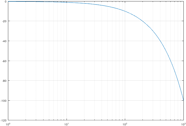
This looks like an ideal Gaussian filter (itself having a much stronger increasing attenuation). If that's what you want, you're stating the problem based on false assumptions: all so-called Gaussian filters are nothing but approximations, and all obey the $N/f$ slope. It can't be any other way, since $\text{e}^{-x^2}$ has infinitely many derivatives. If a Gaussian filter is not what you want then I have to wonder what is your purpose?

History
Why does this post require moderator attention?
You might want to add some details to your flag.

1 comment thread

Comments (2 comments)
Comments
MissMulan‭ wrote almost 2 years ago

In reality yes, but I am assuming that the slope db/Hz is constant.It is for educational purposes only.

a concerned citizen‭ wrote almost 2 years ago

MissMulan‭ Frankly, it sounds quite dishonest for you to ask about the design of the filter, then say it's only for "educational purposes". It's like me, asking for red fruits which taste like avocado because I'm interested in tasing one, only to say after people searched for me that "oh, I was just reading here, in the magazine, and thought of it". Just FYI, such a filter likely does not exist in nature, since, if you look closely, at 1 Hz it's -1 dB,. at 10 Hz it's -10 dB, at 100 Hz -> -100 dB, which would mean -1000 dB @ 1 kHz, which is ridiculous; think of 1 MHz.