Comments on Should I connect signal reference and chassis ground in a battery powered application?
Post
Should I connect signal reference and chassis ground in a battery powered application?
Hello. I have a grounding problem on my acquisition system. I have read many articles, app notes and whatever but still could not find a convincing solution for the topic.
The acquisition system is made of an anodized aluminium box with a PCB inside and two external load cells. More details:
- each load cell:
- is made up with strain gauges in a Wheatstone bridge arrangement
- is connected to the board through a 2.5 meters cable with a metallic cable gland
- has exposed steel parts, which are directly connected to the cable shield, with the other end of the shield connected to PCB screws
- the acquisition system:
- is battery powered (NiMH)
- has a USB input for battery charging
- has a WiFi connection with an external antenna
- is IP65
- passed RED certification
- the box is anodized (insulated), but there are masked sections for external connections (USB connector, power button, mounting screws, cable glands, panel antenna connector) and for the PCB screws inside
- the WiFi antenna connector carries the signal reference on its cold pole
- the antenna cold pole is mounted on the box in a masked section, thus creating a direct connection between signal reference and metal box (chassis ground); the connection is only made in this point
- the acquisition system is battery powered and hence it has no earth ground reference; but it is used in a railway application, and when used the exposed steel parts of the load cells are in direct contact with rails (which are grounded)
After the RED certification phase we shipped a few systems to a lab in order to certificate system measurements, but two systems came back to our lab with some damaged ICs. I suspect an ESD event, as the ADC and LDO converter connected to the load cells were damaged and are not protected against ESD.
Now I am redesigning the system in order to solve this issue. I will definitely add ESD protections and connect the shield of the load cell cables to the cable gland (so as to have a 360 degree coverage). But my main issue is: is it ok to connect signal reference and chassis ground? Should I leave that connection, or it would be better to unmask the panel antenna connection thus separating the two grounds?
As I said, I found many articles on the topic, but none of them mentioned the battery powered case. So I am still a little confused about the possible consequences of both choices.
Thanks in advance for your help.
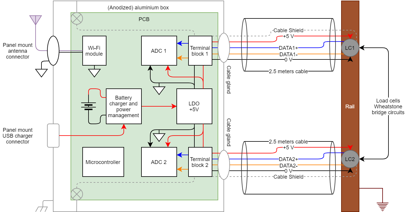
Edit: The following diagram shows my acquisition system (some external devices such as power button are not shown). I tried to make it easier to read by using different colors for different signals:
- black for system reference (PCB ground)
- light gray for chassis ground
- brown for earth ground (on the rail)
- red for positive power lines
- other colors for signals
The panel antenna connector is intrinsecally connected to PCB ground and it is also connected to the chassis ground; at the moment this is the only connection between the two. The traces on the PCB carrying the cable shields to the screws (shown in the diagram) are not connected to PCB ground on the PCB itself.
@Olin Lathrop: from your answer I think I should leave the "mask" on the aluminium box in the panel antenna connector section, so as to use it as the single point connection between system ground and chassis ground. But this leads me to a new implication: what happens when the two load cells are placed on the rail (see diagram) and the chassis ground is bound to be at earth potential? Could it cause some voltage shift I should be aware of?
Edit 2: @Andy aka: the guys at the measurement lab were not able to tell exactly what happened. What I know is they put all systems on a metal table: this creates a second connection between metallic parts (chassis ground) but I think there would be no issue, as this does not affect PCB ground. Even small noise currents circulating on the chassis ground (ground loop created by the two connections) should not be an issue as there is still only one connection point between PCB ground and chassis ground. Moreover, 4 system were used and only two of them got damaged. The load cells are made up with strain gauges and a flexible PCB, so the only insulation between the signals on the Wheatstone bridge and the metal parts on the rail are the strain gauge carrier (a 40 um thick insulating material) and the flexible PCB material (50 um thick). There was no lightning, and an ESD event is my opinion based upon the fact that the LDO and ADCs (not protected against ESD) got destroyed. My first goal is understanding whether or not I should keep PCB ground and chassis ground connected in the point they are now, with a technical explanation about it (and I think Olin's is very clear). The second goal is to understand what can I do to make my system more robust against external events (such as ESD), as the issue happened with PCB and chassis grounds connected.
@Olin Lathrop: "rail" is a single railroad track, sorry for not clarifying this point. The system is used for weighing trains. The sensors have a 2.5 meters cable connecting them to the box. Isolation is one of my options for redesign, but if possibile I would avoid. I already have a microcontroller, and I used isolation in other designs, so this is not a problem, but it would be a major circuit modification, requiring time and efforts. Still, of course, I will go for it if it is my best option.
Thank you all
Stefano
Edit 3: @Olin Lathrop, I owe you some clarifications (and maybe a few more questions):
- the system cannot be used while the USB charger is connected, hence the "battery powered isolation" is always present
- the system is portable and therefore the sensors are positioned on the track only for the time necessary to take the measurements, then they are taken away
- the data wires from the sensors are treated as differential, and are filtered as soon as they enter the circuit, just before the ADC inputs
- the sensors' 0V lines are not directly connected to the cable shields but they are connected to the PCB ground
- the sensors' cable shields are attached to the sensors' metal parts, and the metal parts are connected to the rail when in use; there could not be a direct connection between the cable shields and the rail as the sensors have to be taken away when not in use
- I cannot change the sensors' chassis; I could change the way cable shields are connected to them, but from waht I understand it does not seem to be a good choice
- about ground loops: I took many voltage measurements between different chassis ground points and found no significant voltage (a few uV at most, maybe due to multimeter uncertainty).
Again on 0V lines: they are not directly connected to the cable shields, but the sensors' 0V lines are connected to PCB ground and cable shields are connected to chassis ground. Being PCB and chassis grounds connected in one point, 0V lines get connected to cable shields. Is it ok or should I change something?
And: the "single point connection" between PCB ground and chassis ground is on the panel antenna connector, as the antenna cable - connecting the inside connector to the external antenna - carries the PCB ground and is attached to the box. So basically I have two possible choices for the one point connection between PCB and chassis grounds:
- keep the single point connection on the antenna; for me this is the quickest and easiest way
- do not connect the panel antenna connector to the box and make the single point connection on a PCB screw; this way I see a possible fault in the fact that PCB ground will be accessible both from the antenna connector (isolated from chassis ground) and from chassis ground (connected to PCB ground through the screw), thus giving the way to possible ground loops.
What do you think about that?
Again, thanks for your help.
Edit 4: @Olin Lathrop: From your last sentence I assume that choice 1 above is correct and the load cells' grounding is ok as well. Thanks a lot

1 comment thread