Communities

Writing
Writing
Codidact Meta
Codidact Meta
The Great Outdoors
The Great Outdoors
Photography & Video
Photography & Video
Scientific Speculation
Cooking
Cooking
Electrical Engineering
Judaism
Judaism
Languages & Linguistics
Software Development
Mathematics
Mathematics
Christianity
Christianity
Code Golf
Code Golf
Music
Music
Physics
Physics
Linux Systems
Linux Systems
Power Users
Power Users
Tabletop RPGs
Tabletop RPGs
Community Proposals
Community Proposals
tag:snake search within a tag
answers:0 unanswered questions
user:xxxx search by author id
score:0.5 posts with 0.5+ score
"snake oil" exact phrase
votes:4 posts with 4+ votes
created:<1w created < 1 week ago
post_type:xxxx type of post
Search help
Notifications
Mark all as read See all your notifications »
Q&A

Comments on Burned Source Driver - Noise Spikes from Relay Coil

Post

Burned Source Driver - Noise Spikes from Relay Coil

+3
−0

I am trying to figure out what is causing an Allegro A2982 source driver to burn up.

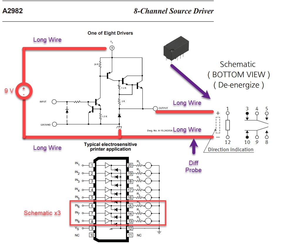
The source driver (A2982) is connected to the coil of a Panasonic TXS2-9V relay. The source driver and coil are connected by about 3 feet of wire. The source driver is on the high side and the coil is on the low side.

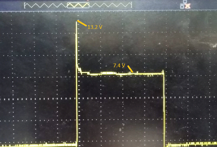
The rail of the source driver (Vs) is 9 V. The source driver output is ~7.4 V. The peak voltage of the spike, measured across the inductor, is ~13.2 V. Note: I am using a differential probe to measure the voltage across the coil.

Waveform

Is it a valid concern that:

  1. This voltage spike is causing damage to the source driver?
  2. The 9V supply may see the voltage spike and cause damage?
  3. The Vbe reverse breakdown voltage of the darlington-pair may be exceeded and cause damage?

If the spike is causing damage, is there a way to reduce or mitigate the spike?

Circuit Schematic Schematic

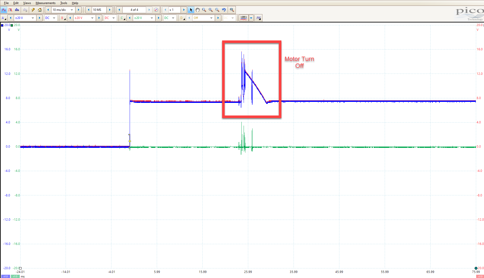
The circuit is used to turn off a motor. Below is a scope capture. The squared area in red is when the motor turns off. The output of the relay controls an ON/OFF signal (3.3V or GND). Note: The relay coils are located near the motor. Three outputs of the source driver are used to drive three separate relay coils.
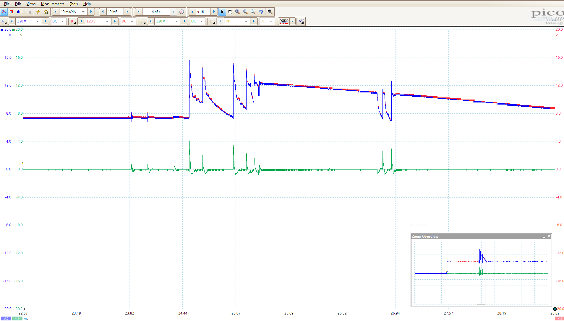
 Capture

Closeup Capture_Closeup

History
Why does this post require moderator attention?
You might want to add some details to your flag.
Why should this post be closed?

2 comment threads

Show a schematic! (5 comments)
Which part is the Darlington? (2 comments)
Show a schematic!
Olin Lathrop‭ wrote 8 months ago

Too much hand waving, too little schematic. I think I know what's going on, but don't want to decipher the word soup to understand the circuit.

mrbean‭ wrote 8 months ago · edited 8 months ago

I attached a schematic and added additional detail. Do the updates need to be approved? I am not seeing my update.

Edit: Looks like I needed to click the submit button twice because it was complaining about "alt text" for the images. I almost lost my work... whoops.

mrbean‭ wrote 8 months ago · edited 8 months ago

Olin Lathrop‭ These relay coils are close to a motor. Do you think magnetic fields and di/dt in the motor windings could be inducing currents in the relay coils? Like a guitar pickup?

mrbean‭ wrote 8 months ago · edited 8 months ago

Olin Lathrop‭ Thank you for the excellent answer! I have had issues with ground bounce due to the motor currents causing issues with other signals. I've had to be careful where I connect grounds of signals fed to an MCU. That very well could be what's happening. I will try investigating that further. I will also try measuring the source driver current and see what the coils are pulling for current. According to the TXS2-9V datasheet the coil resistance is 1620 Ohms and operating current is 5.6 mA. Perhaps these coils are pulling more than expected.

mrbean‭ wrote 8 months ago · edited 8 months ago

Olin Lathrop‭ I hooked up three relay coils directly to the power supply set to 9V. The current read from the power supply was 16.6 mA (16.6 mA / 3 = 5.53 mA). The maximum current read from the DMM was 16.46 mA (16.46 mA / 3 = 5.49). I've switched the relay on and off several times using the output enable on the supply. The relay switches cleanly on the scope. There are no sudden spikes. I assume this probably isn't a fair comparison since the slew rate of the supply is probably slower than the source driver.