Comments on How could a damaged wire in split-phase power delivery create these voltages?
Parent
How could a damaged wire in split-phase power delivery create these voltages?
Recently, my home suffered a partial power outage, and due to curiosity and a desire to learn more about residential AC power, I'm trying to understand how the event that took place resulted in the symptoms I observed.
My home is served by split-phase power from a nearby transformer, single-phase power transformed down to 240V with a center tap. For the sake of explanation I refer to the wires coming from the transformer to the main junction box on my house as L1, L2 and G. L1 and L2 are the "hot" wires, the voltage between which should ideally be 240V. G is the center tap wire, which is grounded and should ideally have a voltage difference of 120V to either of L1 or L2.
When the outage occurred, I observed the following:
- The L1/G voltage difference was 120V (good).
- The G/L2 voltage difference was 90V (bad).
- The L1/L2 voltage difference was 30V (very bad!).
Despite my taking these measurements with a generic digital multimeter with a 10 MΩ input impedance (which I'm told is not reliable for this case), I believe them to be accurate as the power company repairmen also made measurements and confirmed that theirs matched my own.
The power company repairman investigated and determined that someone had been digging nearby and nicked the insulation to the L2 cable going from the transformer to my house. He said that this damage resulted in corrosion and build-up of mineral residue from electrolysis, and that the result was that impedance of the L2 cable increased drastically. (This cable was actually a cluster of several thick wires, and he said that sometimes in cases like this the corrosion is so bad that only 2 of the wires in the cluster remain fully intact.)
What I don't understand is how that can result in those voltage measurements. I can understand how high impedance on L2 could cause a drop in the L1/L2 voltage, and how L1/G could remain 120V since the high impedance of L2 would not be a part of the L1/G circuit. But I'm thoroughly puzzled by how the L1/L2 voltage of 30V can be lower than the G/L2 voltage of 90V; it seems like both voltages to the center tap, namely L1/G and G/L2, should sum up to L1/L2... unless some kind of really weird voltage phase shift is going on.
Any answers that could educate me in the aspects of AC electrical power that might explain this would be greatly appreciated!
Post
Well, here is was my logic tells me:
The corrosion has caused a high impedance in the L2 wire, but there should be also a "short" between the L1 and L2 wire. So that the voltage between L1 and L2 falls to 30V, and the voltage between G and L1 is 90V. In other words:
L1 - G = 120V = L1 - L2 + L2 - G = 30 + 90 = 120.
In the shematic below, I've noted +120V AC and -120V AC just to say that the voltage is in phase opposition.
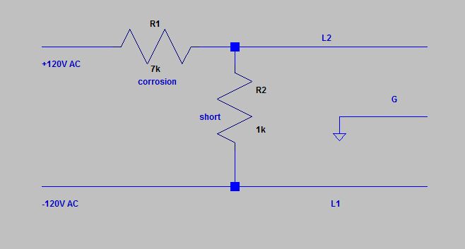
One way to check that would be to scope the voltages together at L1 and L2 to observe that L1 and L2 are no more in phase opposition, but close to be in phase concordance. Also, it would be interesting to check the corrosion impedance of the L2 wire. In the schematic, I've given imaginary values, the point being that there is a ratio of 1:7 between the resistances:
30V = 240V / 8 = 240V / (1 + 7).

0 comment threads