Post History
I'm trying to understand a circuit for driving a LED found on a board I purchased. Below is the circuit driven by an I/O pin (HS2) of a small 3.3V processor. The HS2 pin is driven by the I/O wi...
#11: Post edited
by
 Lorenzo Donati
·
2023-08-09T19:02:01Z (almost 2 years ago)
Lorenzo Donati
·
2023-08-09T19:02:01Z (almost 2 years ago)
Retagged.
#10: Post edited
by
Lorenzo Donati
·
2023-07-28T20:46:35Z (almost 2 years ago)
Reformatted for better readability. Some minor grammar and wording adjustments.
Trying to understand a circuit for driving a LED found on a board I purchased.Below is a circuit driven by an I/O pin (HS2) of a small 3.3V processor.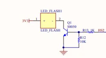The HS2 pin is driven by the I/O with specs of V(high) = .8(Vsupply) = 2.64V, and V(low) = .1(Vsupply) = .33V . The I/O pin can be set to drive up to 28 ma, but I am guessing the design of the circuit would rather pull the current from Vsupply rather than the I/O controlling pin (HS2), and that is the reason for using the npn transistor (S8050) to drive the LED.The LED is a SMD 3528 white that I do not have specs on, but testing shows it lights up nicely at 40ma, and does fine at 11ma, with 3.24v across the LED.I am wondering if the reason for this design is because this bright white LED is typically looking for a 3V drop, and if they used a current limiting resistor in series with the LED, then maybe the resistor would drop too much voltage and bring the volts across the LED to less than 3?How is the 1K / 10K voltage divider working to set the current through the flash? Does this circuit seem like a good one to duplicate if I wanted to create additional LED's driven by other pins on the processor? When the transistor is on, is it setting the current, or will the current vary per the gain of the transistor? I see how this circuit is acting as a switch, but is also fixing the current through the led, or is the current through the led dependent on the gain of the transistor.
- I'm trying to understand a circuit for driving a LED found on a board I purchased.
- Below is the circuit driven by an I/O pin (HS2) of a small 3.3V processor.
- 
- The HS2 pin is driven by the I/O with these specs:
- **V(high) = 0.8 · V<sub>supply</sub> = 2.64 V**
- **V(low) = 0.1 · V<sub>supply</sub> = 0.33 V**
- The I/O pin can be set to drive up to 28 mA, but I am guessing the design of the circuit would rather pull the current from V<sub>supply</sub> rather than the I/O controlling pin (HS2), and that is the reason for using the NPN transistor (S8050) to drive the LED.
- The LED is a SMD 3528 white LED for which I do not have specs, but testing shows it lights up nicely at 40 mA, and does fine at 11 mA, with 3.24 V across.
- I am wondering if the reason for this design is because this bright white LED is typically looking for a 3 V drop, and if they used a current limiting resistor in series with the LED, then maybe the resistor would drop too much and bring the voltage across the LED to less than 3 V.
- How is the 1k/10k voltage divider working to set the current through the flash?
- Does this circuit seem like a good one to duplicate if I wanted to create additional LEDs driven by other pins on the processor?
- When the transistor is on, is it setting the current, or will the current vary per the gain of the transistor?
- I see how this circuit is acting as a switch, but is it also fixing the current through the LED? Or is the current through the LED dependent on the gain of the transistor?
#9: Post edited
by
 Olin Lathrop
·
2020-06-16T13:08:30Z (almost 5 years ago)
Olin Lathrop
·
2020-06-16T13:08:30Z (almost 5 years ago)
- Trying to understand a circuit for driving a LED found on a board I purchased.
- Below is a circuit driven by an I/O pin (HS2) of a small 3.3V processor.
- 
- The HS2 pin is driven by the I/O with specs of V(high) = .8(Vsupply) = 2.64V, and V(low) = .1(Vsupply) = .33V . The I/O pin can be set to drive up to 28 ma, but I am guessing the design of the circuit would rather pull the current from Vsupply rather than the I/O controlling pin (HS2), and that is the reason for using the npn transistor (S8050) to drive the LED.
- The LED is a SMD 3528 white that I do not have specs on, but testing shows it lights up nicely at 40ma, and does fine at 11ma, with 3.24v across the LED.
- I am wondering if the reason for this design is because this bright white LED is typically looking for a 3V drop, and if they used a current limiting resistor in series with the LED, then maybe the resistor would drop too much voltage and bring the volts across the LED to less than 3?
How is the 1K / 10K voltage divider working to set the current through the flash? Does this circuit seem like a good one to duplicate if I wanted to create additional LED's driven by other pins on the processor? When the transistor is on, is it setting the current, or will the current vary per the gain of the transistor? I see how this circuit is acting as a switch, but is also fixing the current through the led, or is the current through the led dependent on the gain of the transistor.(also, I wanted to use different tags, but currently I think I can only select among 3 drop-down choices)
- Trying to understand a circuit for driving a LED found on a board I purchased.
- Below is a circuit driven by an I/O pin (HS2) of a small 3.3V processor.
- 
- The HS2 pin is driven by the I/O with specs of V(high) = .8(Vsupply) = 2.64V, and V(low) = .1(Vsupply) = .33V . The I/O pin can be set to drive up to 28 ma, but I am guessing the design of the circuit would rather pull the current from Vsupply rather than the I/O controlling pin (HS2), and that is the reason for using the npn transistor (S8050) to drive the LED.
- The LED is a SMD 3528 white that I do not have specs on, but testing shows it lights up nicely at 40ma, and does fine at 11ma, with 3.24v across the LED.
- I am wondering if the reason for this design is because this bright white LED is typically looking for a 3V drop, and if they used a current limiting resistor in series with the LED, then maybe the resistor would drop too much voltage and bring the volts across the LED to less than 3?
- How is the 1K / 10K voltage divider working to set the current through the flash? Does this circuit seem like a good one to duplicate if I wanted to create additional LED's driven by other pins on the processor? When the transistor is on, is it setting the current, or will the current vary per the gain of the transistor? I see how this circuit is acting as a switch, but is also fixing the current through the led, or is the current through the led dependent on the gain of the transistor.
#8: Post edited
by
Olin Lathrop
·
2020-06-16T13:07:02Z (almost 5 years ago)
#7: Post edited
by
Olin Lathrop
·
2020-06-16T13:06:27Z (almost 5 years ago)
#6: Post edited
by
Olin Lathrop
·
2020-06-16T13:06:14Z (almost 5 years ago)
#5: Post edited
by
Olin Lathrop
·
2020-06-16T13:04:43Z (almost 5 years ago)
#4: Post edited
by
 Monica Cellio
·
2020-06-16T01:26:00Z (almost 5 years ago)
Monica Cellio
·
2020-06-16T01:26:00Z (almost 5 years ago)
adding tags requested by OP
#3: Post edited
by
 eric
·
2020-06-16T00:43:12Z (almost 5 years ago)
eric
·
2020-06-16T00:43:12Z (almost 5 years ago)
- Trying to understand a circuit for driving a LED found on a board I purchased.
- Below is a circuit driven by an I/O pin (HS2) of a small 3.3V processor.
- 
- The HS2 pin is driven by the I/O with specs of V(high) = .8(Vsupply) = 2.64V, and V(low) = .1(Vsupply) = .33V . The I/O pin can be set to drive up to 28 ma, but I am guessing the design of the circuit would rather pull the current from Vsupply rather than the I/O controlling pin (HS2), and that is the reason for using the npn transistor (S8050) to drive the LED.
- The LED is a SMD 3528 white that I do not have specs on, but testing shows it lights up nicely at 40ma, and does fine at 11ma, with 3.24v across the LED.
- I am wondering if the reason for this design is because this bright white LED is typically looking for a 3V drop, and if they used a current limiting resistor in series with the LED, then maybe the resistor would drop too much voltage and bring the volts across the LED to less than 3?
How is the 1K / 10K voltage divider working to set the current through the flash? Does this circuit seem like a good one to duplicate if I wanted to create additional LED's driven by other pins on the processor? When the transistor is on, is it setting the current, or will the current vary per the gain of the transistor? I see how this circuit is acting as a switch, but is also fixing the current through the led, or is the current through the led dependent on the gain of the transistor.
- Trying to understand a circuit for driving a LED found on a board I purchased.
- Below is a circuit driven by an I/O pin (HS2) of a small 3.3V processor.
- 
- The HS2 pin is driven by the I/O with specs of V(high) = .8(Vsupply) = 2.64V, and V(low) = .1(Vsupply) = .33V . The I/O pin can be set to drive up to 28 ma, but I am guessing the design of the circuit would rather pull the current from Vsupply rather than the I/O controlling pin (HS2), and that is the reason for using the npn transistor (S8050) to drive the LED.
- The LED is a SMD 3528 white that I do not have specs on, but testing shows it lights up nicely at 40ma, and does fine at 11ma, with 3.24v across the LED.
- I am wondering if the reason for this design is because this bright white LED is typically looking for a 3V drop, and if they used a current limiting resistor in series with the LED, then maybe the resistor would drop too much voltage and bring the volts across the LED to less than 3?
- How is the 1K / 10K voltage divider working to set the current through the flash? Does this circuit seem like a good one to duplicate if I wanted to create additional LED's driven by other pins on the processor? When the transistor is on, is it setting the current, or will the current vary per the gain of the transistor? I see how this circuit is acting as a switch, but is also fixing the current through the led, or is the current through the led dependent on the gain of the transistor.
- (also, I wanted to use different tags, but currently I think I can only select among 3 drop-down choices)
#2: Post edited
by
eric
·
2020-06-16T00:41:31Z (almost 5 years ago)
- Trying to understand a circuit for driving a LED found on a board I purchased.
- Below is a circuit driven by an I/O pin (HS2) of a small 3.3V processor.
- 
- The HS2 pin is driven by the I/O with specs of V(high) = .8(Vsupply) = 2.64V, and V(low) = .1(Vsupply) = .33V . The I/O pin can be set to drive up to 28 ma, but I am guessing the design of the circuit would rather pull the current from Vsupply rather than the I/O controlling pin (HS2), and that is the reason for using the npn transistor (S8050) to drive the LED.
- The LED is a SMD 3528 white that I do not have specs on, but testing shows it lights up nicely at 40ma, and does fine at 11ma, with 3.24v across the LED.
I am wondering if the reason for this design is because this bright white LED is typically looking for a 3V drop, and if they used a current limiting resistor in series with the LED, then maybe the resistor would drop too much voltage and bring the volts accross the LED to less than 3?How is the 1K / 10K voltage divider working to set the current through the flash? Does this circuit seem like a good one to duplicate if I wanted to create additional LED's driven by other pins on the processor?
- Trying to understand a circuit for driving a LED found on a board I purchased.
- Below is a circuit driven by an I/O pin (HS2) of a small 3.3V processor.
- 
- The HS2 pin is driven by the I/O with specs of V(high) = .8(Vsupply) = 2.64V, and V(low) = .1(Vsupply) = .33V . The I/O pin can be set to drive up to 28 ma, but I am guessing the design of the circuit would rather pull the current from Vsupply rather than the I/O controlling pin (HS2), and that is the reason for using the npn transistor (S8050) to drive the LED.
- The LED is a SMD 3528 white that I do not have specs on, but testing shows it lights up nicely at 40ma, and does fine at 11ma, with 3.24v across the LED.
- I am wondering if the reason for this design is because this bright white LED is typically looking for a 3V drop, and if they used a current limiting resistor in series with the LED, then maybe the resistor would drop too much voltage and bring the volts across the LED to less than 3?
- How is the 1K / 10K voltage divider working to set the current through the flash? Does this circuit seem like a good one to duplicate if I wanted to create additional LED's driven by other pins on the processor? When the transistor is on, is it setting the current, or will the current vary per the gain of the transistor? I see how this circuit is acting as a switch, but is also fixing the current through the led, or is the current through the led dependent on the gain of the transistor.
#1: Initial revision
by
eric
·
2020-06-15T23:31:47Z (almost 5 years ago)
Trying to understand a circuit for driving a LED found on a board I purchased. Below is a circuit driven by an I/O pin (HS2) of a small 3.3V processor.  The HS2 pin is driven by the I/O with specs of V(high) = .8(Vsupply) = 2.64V, and V(low) = .1(Vsupply) = .33V . The I/O pin can be set to drive up to 28 ma, but I am guessing the design of the circuit would rather pull the current from Vsupply rather than the I/O controlling pin (HS2), and that is the reason for using the npn transistor (S8050) to drive the LED. The LED is a SMD 3528 white that I do not have specs on, but testing shows it lights up nicely at 40ma, and does fine at 11ma, with 3.24v across the LED. I am wondering if the reason for this design is because this bright white LED is typically looking for a 3V drop, and if they used a current limiting resistor in series with the LED, then maybe the resistor would drop too much voltage and bring the volts accross the LED to less than 3? How is the 1K / 10K voltage divider working to set the current through the flash? Does this circuit seem like a good one to duplicate if I wanted to create additional LED's driven by other pins on the processor?