Post History
This application note from Linear Technology discusses oscillations in opamp circuits and some compensation schemes. One method discussed for reducing phase shifts in the loop gain due to the RC ne...
#2: Post edited
by
 Lorenzo Donati
·
2023-08-09T21:28:56Z (almost 2 years ago)
Lorenzo Donati
·
2023-08-09T21:28:56Z (almost 2 years ago)
Retagged.
#1: Initial revision
by
 rpm_2718
·
2020-08-08T13:14:11Z (almost 5 years ago)
rpm_2718
·
2020-08-08T13:14:11Z (almost 5 years ago)
Amplifier compensation with added resistor across opamp input terminals
This [application note](https://www.analog.com/media/en/technical-documentation/application-notes/an148fa.pdf) from Linear Technology discusses oscillations in opamp circuits and some compensation schemes. One method discussed for reducing phase shifts in the loop gain due to the RC network formed by the feedback network and the opamp input capacitance is shown below for a non-inverting configuration, in which a resistor \$R_{IN}\$ is added between the opamp input terminals:
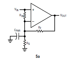
The added resistor \$R_{IN}\$ reduces the resistance of the divider network as seen by the opamp terminal (assuming a low-source resistance at Vin), pushing the pole formed by the input capacitance and the feedback resistance to higher frequency. This part is easy to understand.
I am looking for help understanding the statement that I have highlighted in the paragraph below that explains the circuit in the app note:
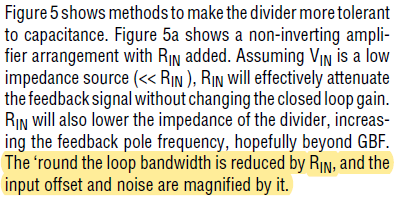
This feedback network appears to be a combination of series and shunt feedback on the input side. I am unclear about how to analyze this circuit from a feedback perspective to understand the highlighted statement.
If you can help point me in the right direction, you can assume an understanding of feedback analysis of common topologies such as inverting and non-inverting configurations. If a detailed explanation is a bit cumbersome, intuitive discussion would be helpful too.