Post History
I am having a difficult time picturing the flow of current and the role of the capacitor during the OFF time of a buck converter. Here is my understanding so far. During the ON time the magnetic fi...
#2: Post edited
Hello,- I am having a difficult time picturing the flow of current and the role of the capacitor during the OFF time of a buck converter. Here is my understanding so far. During the ON time the magnetic field of the inductor grows and positive charge is being stored on the top plate of the capacitor as well as current being delivered to the load. The load sees a somewhat smooth but ramping voltage because the capacitor is resisting a change in voltage by sucking some current to charge up.
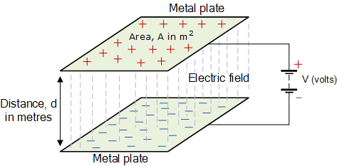
- When the switch is OFF, the polarity reverses, and the collapsing magnetic field continues to supply current to the load. Here is where I can't visualize how current is flowing through the flywheel loop - I picture the charged capacitor with the positive charge on the top plate and the negative charge on the bottom plate like the picture below:
- 
Now how does the positive charge supplied by the inductor flow through the capacitor, through the diode, and back to the negative side of the inductor when there is a dielectric blocking it? Additionally, how is the current supplied to the load during this OFF period? Does the capacitor supply current to the load in tandem with the collapsing magnetic field, or is it either the inductor or the capacitor that is supplying current to the load? If the voltage is decreasing during this OFF time based on that classic zig-zag output shape, then it seems to me that at least the capacitor is definitely supplying current to the load.Thanks for clearing up the fog.
- I am having a difficult time picturing the flow of current and the role of the capacitor during the OFF time of a buck converter. Here is my understanding so far. During the ON time the magnetic field of the inductor grows and positive charge is being stored on the top plate of the capacitor as well as current being delivered to the load. The load sees a somewhat smooth but ramping voltage because the capacitor is resisting a change in voltage by sucking some current to charge up.
- When the switch is OFF, the polarity reverses, and the collapsing magnetic field continues to supply current to the load. Here is where I can't visualize how current is flowing through the flywheel loop - I picture the charged capacitor with the positive charge on the top plate and the negative charge on the bottom plate like the picture below:
- 
- Now how does the positive charge supplied by the inductor flow through the capacitor, through the diode, and back to the negative side of the inductor when there is a dielectric blocking it? Additionally, how is the current supplied to the load during this OFF period? Does the capacitor supply current to the load in tandem with the collapsing magnetic field, or is it either the inductor or the capacitor that is supplying current to the load? If the voltage is decreasing during this OFF time based on that classic zig-zag output shape, then it seems to me that at least the capacitor is definitely supplying current to the load.
#1: Initial revision
Current Flow in the OFF Time of a Switching Power Supply
Hello, I am having a difficult time picturing the flow of current and the role of the capacitor during the OFF time of a buck converter. Here is my understanding so far. During the ON time the magnetic field of the inductor grows and positive charge is being stored on the top plate of the capacitor as well as current being delivered to the load. The load sees a somewhat smooth but ramping voltage because the capacitor is resisting a change in voltage by sucking some current to charge up. When the switch is OFF, the polarity reverses, and the collapsing magnetic field continues to supply current to the load. Here is where I can't visualize how current is flowing through the flywheel loop - I picture the charged capacitor with the positive charge on the top plate and the negative charge on the bottom plate like the picture below:  Now how does the positive charge supplied by the inductor flow through the capacitor, through the diode, and back to the negative side of the inductor when there is a dielectric blocking it? Additionally, how is the current supplied to the load during this OFF period? Does the capacitor supply current to the load in tandem with the collapsing magnetic field, or is it either the inductor or the capacitor that is supplying current to the load? If the voltage is decreasing during this OFF time based on that classic zig-zag output shape, then it seems to me that at least the capacitor is definitely supplying current to the load. Thanks for clearing up the fog.


