Antenna Feed Line Question
Hello,
I am designing 1/4 WL strip antenna for a bluetooth chip and i had some questions regarding the 50 Ohm feed line.
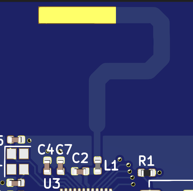
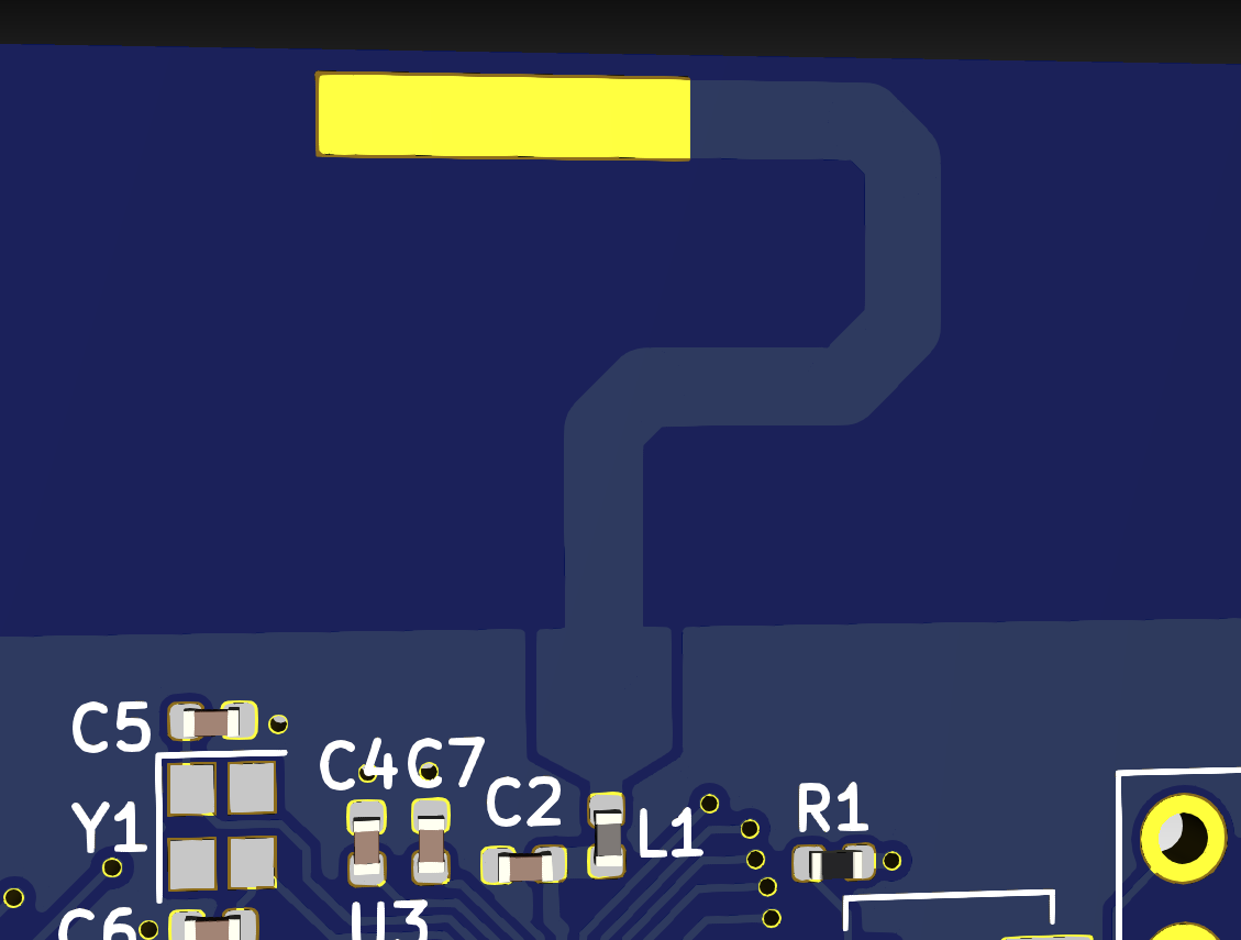
Right now I am using a Nordic-recommended 1.5mm trace width and a 23mm + 4mm(for tuning purposes) trace length as my antenna. My feed line is 2mm away from the antenna and the microstrip calculator I am using has recommended me ~3mm as the width of the feed line. Since this feed-line width is so large relative to the 2mm distance away from the antenna, I have just made the feed line the size of the pads of the matching network. My question is - can I get away with fudging it like this, or must I draw the ground plane out further so I can accommodate that 3mm feed line?
In the first picture below, I am not using the 3mm feed line but am making it as large as the matching network smd pads can accommodate. In the second picture, I am drawing out the ground plane in order to have enough room for the 3mm trace width. Which is less likely to jack it all up? Thanks.
1 answer
Any deviation from the example antenna could have significant and unintuitive consequences. Unless you have good antenna modeling software and good understanding of antenna physics (which you apparently don't since you're asking here), don't deviate from the suggested design. This includes the exact PC board material and thickness.
Even with the right software and understanding, it's an iterative process. All real world details can't be modeled, and there are variations anyway. Modeling can get you some good ideas to try, but in the end only experimental results can tell you what the antenna really does.
Also, as @Lundin alluded to in a comment, if you are making your own antenna, then compliance testing gets more complicated and expensive. This is one reason whole modules are popular when it comes to RF transmitters. The module manufacturer has already gotten certification for the module as a whole. As long as you follow whatever use restrictions they specify, you don't need to get as much certification yourself.
The short answer for anyone who needs to ask this kind of question on the 'net is to go buy a pre-certified module.
0 comment threads

1 comment thread