Post History
Imagine a battery pack with <=60VDC of maximum voltage and a load of up to 10kW of power(the PMSM inverter with the input capacitance of up to 1mF). The load is not always known - could be 100uF...
#2: Post edited
by
 2kind
·
2020-12-04T22:34:47Z (over 4 years ago)
2kind
·
2020-12-04T22:34:47Z (over 4 years ago)
Added pictures and changed the questions
I've been doing this for quite a while and although could be the typical engineering reaction, I would like to sense check it with more experienced people here.Imagine a battery pack with <=60VDC of maximum voltage to keep it in the LVD domain and a load of up to 10kW of power(the PMSM inverter with the input capacitance of up to 1.000,00 uF). The load is switched on/off using N channel Mosfets, there are no relays present in the circuit. Since there is no galvanic isolation present in the system peripheral communication interfaces(i.e. RS485/CAN) share the same GND as the load.The "usual" way of doing the switching is to put the N channel FET on the battery positive terminal and control it using the gate driver.-----1. What would be the side-effect of placing the N FET on the GND side and move the gate driver out of the equation?2. Could this sudden disconnection of the GND cause potential damage to the CAN or RS485 transceivers?3. Is there any way to do this in a safe manner?
- Imagine a battery pack with <=60VDC of maximum voltage and a load of up to 10kW of power(the PMSM inverter with the input capacitance of up to 1mF). The load is not always known - could be 100uF-1000uF input capacitance while the currents usually range from 20A up until 150A. The load is switched on/off using N channel Mosfets. Since there is no galvanic isolation present in the system peripheral communication interfaces(i.e. RS485/CAN) share the same GND as the load.
- **Approach 1)**
- 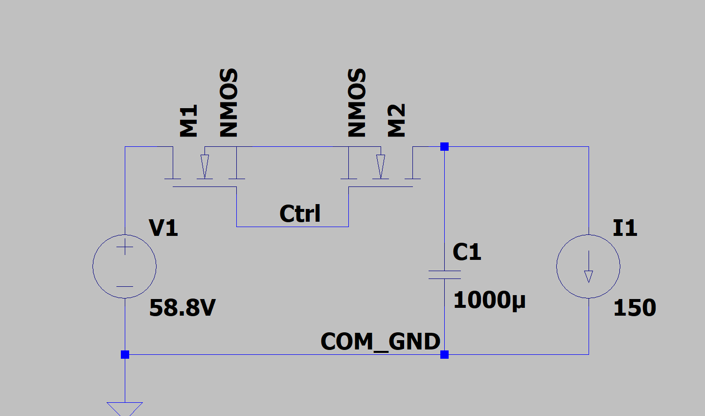
- Switch the high side. Put FETs on the high side and control the "ctrl" net using gate drivers. The communication interface(RS485/CAN) is referenced to the "COM_GND" net.
- **Approach 2)**
- 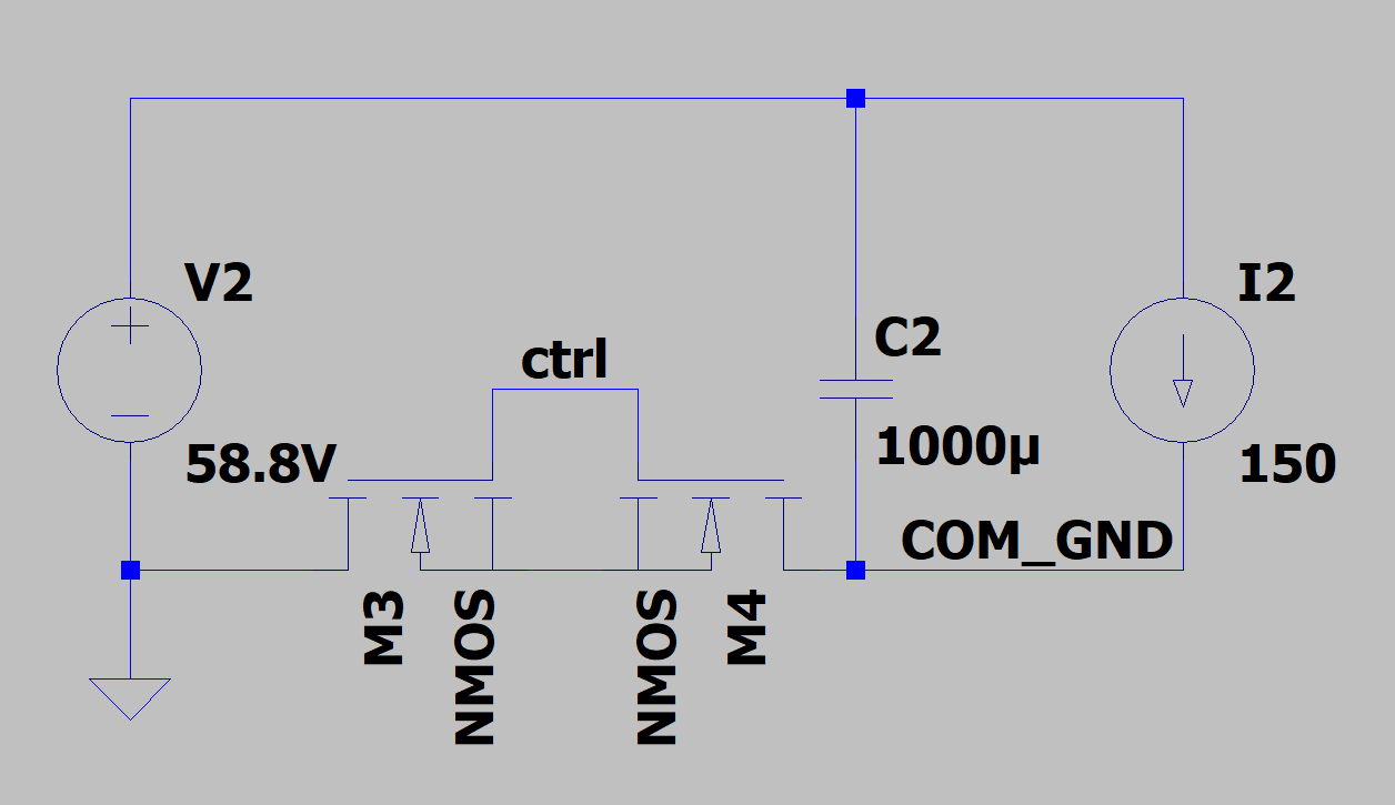
- Switch the low side. Put FETs on the low side and control the "ctrl" net using a 12V switch without gate drivers. However, in this case, the communication interface is referenced to the "COM_GND" net.
- Note: Precharge circuit is present but omitted from the schematic
- 1. Is there a superior architecture approach in this case?
- 2. Could "Approach 2)" harm any of the components due to the ground reference loss?
#1: Initial revision
by
2kind
·
2020-12-04T21:14:51Z (over 4 years ago)
High Power Switch - High Side vs. Low Side Switching
I've been doing this for quite a while and although could be the typical engineering reaction, I would like to sense check it with more experienced people here.

Imagine a battery pack with <=60VDC of maximum voltage to keep it in the LVD domain and a load of up to 10kW of power(the PMSM inverter with the input capacitance of up to 1.000,00 uF). The load is switched on/off using N channel Mosfets, there are no relays present in the circuit. Since there is no galvanic isolation present in the system peripheral communication interfaces(i.e. RS485/CAN) share the same GND as the load.

The "usual" way of doing the switching is to put the N channel FET on the battery positive terminal and control it using the gate driver.


-----


 1. What would be the side-effect of placing the N FET on the GND side and move the gate driver out of the equation?
2. Could this sudden disconnection of the GND cause potential damage to the CAN or RS485 transceivers?
3. Is there any way to do this in a safe manner?