Post History
In the block diagram of this pulse oximeter design guide , in page 6, I see that the system utilizes two analog filters, one for filtering the PPG signal generated while the RED light/wavelength is...
#4: Post edited
by
 Georgian
·
2021-01-30T13:48:30Z (over 4 years ago)
Georgian
·
2021-01-30T13:48:30Z (over 4 years ago)
added another image to justify a statement
- In the block diagram of [this pulse oximeter design guide](https://www.nxp.com/docs/en/application-note/AN4327.pdf) , in page 6, I see that the system utilizes two analog filters, one for filtering the PPG signal generated while the RED light/wavelength is 'ON',
- and one for filtering the signal generated while the IR light is ON.
- [](https://electrical.codidact.com/uploads/QPWNzhXHjEiSNffSP67g2Yxn)
- Specifically the process is as follows: The photodiode which plays the role of the PPG sensor, converts the incoming light to a photocurent - one wavelength at a time, and each respective current is then converted to a voltage through a transimpedance amplifier which also amplifies and low pass filters the signal. The signal "transimpedanceOut" is then demultiplexed into two signal lines "transimpedanceIR" and "transimpedanceRed" that are further filtered and amplified, only to be multiplexed back into a single line to be fed into an ADC.
- I notice however by looking at the schematic that the two filters are completely identical.
- Which begs the **question**: Why not use a single filter in the signal line, saving space and component cost and then time-demultiplex the filtered signal at seperate ADCs based on which wavelength is on each time? Or even without using a demultiplexer, one could simply pass the signal to an ADC which stores the sampled values in two seperate buffers based on which wavelength is sampled each time... What I'd like to know is if this was an unimportant design decision or was it purposefully implemented this way to eliminate some sort of interference/mixing of the two signals (especially if the sampling is fast, i.e each wavelength is ON for 1us at a time).
- In the block diagram of [this pulse oximeter design guide](https://www.nxp.com/docs/en/application-note/AN4327.pdf) , in page 6, I see that the system utilizes two analog filters, one for filtering the PPG signal generated while the RED light/wavelength is 'ON',
- and one for filtering the signal generated while the IR light is ON.
- [](https://electrical.codidact.com/uploads/QPWNzhXHjEiSNffSP67g2Yxn)
- Specifically the process is as follows: The photodiode which plays the role of the PPG sensor, converts the incoming light to a photocurent - one wavelength at a time, and each respective current is then converted to a voltage through a transimpedance amplifier which also amplifies and low pass filters the signal. The signal "transimpedanceOut" is then demultiplexed into two signal lines "transimpedanceIR" and "transimpedanceRed" that are further filtered and amplified, only to be multiplexed back into a single line to be fed into an ADC.
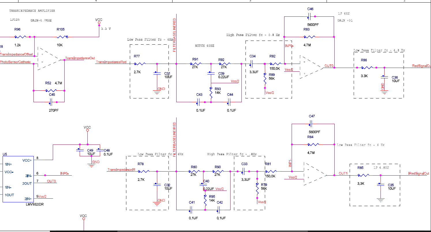
- **EDIT** (based on Olin's answer): Snapshot of pasrt of schematic I found online, presumably for the same design, indicating what I think is the singal being demultiplexed after the transimpedance amp into two seperate lines for RED and IR.
- [](https://electrical.codidact.com/uploads/H6ztYHKLqoiMS1keK23Bu5pz)
- I notice however by looking at the schematic that the two filters are completely identical.
- Which begs the **question**: Why not use a single filter in the signal line, saving space and component cost and then time-demultiplex the filtered signal at seperate ADCs based on which wavelength is on each time? Or even without using a demultiplexer, one could simply pass the signal to an ADC which stores the sampled values in two seperate buffers based on which wavelength is sampled each time... What I'd like to know is if this was an unimportant design decision or was it purposefully implemented this way to eliminate some sort of interference/mixing of the two signals (especially if the sampling is fast, i.e each wavelength is ON for 1us at a time).
#3: Post edited
by
 Pete W
·
2021-01-29T18:12:35Z (over 4 years ago)
Pete W
·
2021-01-29T18:12:35Z (over 4 years ago)
made the pic a hyperlink to full size of itself
Why are two identical filters required for each signal, if the signals can be multiplexed into a single filter?
- In the block diagram of [this pulse oximeter design guide](https://www.nxp.com/docs/en/application-note/AN4327.pdf) , in page 6, I see that the system utilizes two analog filters, one for filtering the PPG signal generated while the RED light/wavelength is 'ON',
- and one for filtering the signal generated while the IR light is ON.
- Specifically the process is as follows: The photodiode which plays the role of the PPG sensor, converts the incoming light to a photocurent - one wavelength at a time, and each respective current is then converted to a voltage through a transimpedance amplifier which also amplifies and low pass filters the signal. The signal "transimpedanceOut" is then demultiplexed into two signal lines "transimpedanceIR" and "transimpedanceRed" that are further filtered and amplified, only to be multiplexed back into a single line to be fed into an ADC.
- I notice however by looking at the schematic that the two filters are completely identical.
- Which begs the **question**: Why not use a single filter in the signal line, saving space and component cost and then time-demultiplex the filtered signal at seperate ADCs based on which wavelength is on each time? Or even without using a demultiplexer, one could simply pass the signal to an ADC which stores the sampled values in two seperate buffers based on which wavelength is sampled each time... What I'd like to know is if this was an unimportant design decision or was it purposefully implemented this way to eliminate some sort of interference/mixing of the two signals (especially if the sampling is fast, i.e each wavelength is ON for 1us at a time).
- In the block diagram of [this pulse oximeter design guide](https://www.nxp.com/docs/en/application-note/AN4327.pdf) , in page 6, I see that the system utilizes two analog filters, one for filtering the PPG signal generated while the RED light/wavelength is 'ON',
- and one for filtering the signal generated while the IR light is ON.
- [](https://electrical.codidact.com/uploads/QPWNzhXHjEiSNffSP67g2Yxn)
- Specifically the process is as follows: The photodiode which plays the role of the PPG sensor, converts the incoming light to a photocurent - one wavelength at a time, and each respective current is then converted to a voltage through a transimpedance amplifier which also amplifies and low pass filters the signal. The signal "transimpedanceOut" is then demultiplexed into two signal lines "transimpedanceIR" and "transimpedanceRed" that are further filtered and amplified, only to be multiplexed back into a single line to be fed into an ADC.
- I notice however by looking at the schematic that the two filters are completely identical.
- Which begs the **question**: Why not use a single filter in the signal line, saving space and component cost and then time-demultiplex the filtered signal at seperate ADCs based on which wavelength is on each time? Or even without using a demultiplexer, one could simply pass the signal to an ADC which stores the sampled values in two seperate buffers based on which wavelength is sampled each time... What I'd like to know is if this was an unimportant design decision or was it purposefully implemented this way to eliminate some sort of interference/mixing of the two signals (especially if the sampling is fast, i.e each wavelength is ON for 1us at a time).
#2: Post edited
by
Georgian
·
2021-01-28T22:03:30Z (over 4 years ago)
small typo
- In the block diagram of [this pulse oximeter design guide](https://www.nxp.com/docs/en/application-note/AN4327.pdf) , in page 6, I see that the system utilizes two analog filters, one for filtering the PPG signal generated while the RED light/wavelength is 'ON',
- and one for filtering the signal generated while the IR light is ON.
- 
- Specifically the process is as follows: The photodiode which plays the role of the PPG sensor, converts the incoming light to a photocurent - one wavelength at a time, and each respective current is then converted to a voltage through a transimpedance amplifier which also amplifies and low pass filters the signal. The signal "transimpedanceOut" is then demultiplexed into two signal lines "transimpedanceIR" and "transimpedanceRed" that are further filtered and amplified, only to be multiplexed back into a single line to be fed into an ADC.
- I notice however by looking at the schematic that the two filters are completely identical.
Which begs the **question**: Why not use a single filter in the signal line, saving space and component cost and then time-demultiplex the filtered signal at seperate ADCs based on which wavelength is on each time? Or even without using a demultiplexer, one could simply pass the signal to an ADC which stores the sampled values in two seperate buffers based on which wavelength is sampled each time... What I'd like to know is if this was an unimportant deisgn decision or was it purposefully implemented this way to eliminate some sort of interference/mixing of the two signals (especially if the sampling is fast).
- In the block diagram of [this pulse oximeter design guide](https://www.nxp.com/docs/en/application-note/AN4327.pdf) , in page 6, I see that the system utilizes two analog filters, one for filtering the PPG signal generated while the RED light/wavelength is 'ON',
- and one for filtering the signal generated while the IR light is ON.
- 
- Specifically the process is as follows: The photodiode which plays the role of the PPG sensor, converts the incoming light to a photocurent - one wavelength at a time, and each respective current is then converted to a voltage through a transimpedance amplifier which also amplifies and low pass filters the signal. The signal "transimpedanceOut" is then demultiplexed into two signal lines "transimpedanceIR" and "transimpedanceRed" that are further filtered and amplified, only to be multiplexed back into a single line to be fed into an ADC.
- I notice however by looking at the schematic that the two filters are completely identical.
- Which begs the **question**: Why not use a single filter in the signal line, saving space and component cost and then time-demultiplex the filtered signal at seperate ADCs based on which wavelength is on each time? Or even without using a demultiplexer, one could simply pass the signal to an ADC which stores the sampled values in two seperate buffers based on which wavelength is sampled each time... What I'd like to know is if this was an unimportant design decision or was it purposefully implemented this way to eliminate some sort of interference/mixing of the two signals (especially if the sampling is fast, i.e each wavelength is ON for 1us at a time).
#1: Initial revision
by
Georgian
·
2021-01-28T18:22:44Z (over 4 years ago)
Why are two identical filters required for each signal, if the signals can be multiplexed into a single filter?
In the block diagram of [this pulse oximeter design guide](https://www.nxp.com/docs/en/application-note/AN4327.pdf) , in page 6, I see that the system utilizes two analog filters, one for filtering the PPG signal generated while the RED light/wavelength is 'ON', and one for filtering the signal generated while the IR light is ON.  Specifically the process is as follows: The photodiode which plays the role of the PPG sensor, converts the incoming light to a photocurent - one wavelength at a time, and each respective current is then converted to a voltage through a transimpedance amplifier which also amplifies and low pass filters the signal. The signal "transimpedanceOut" is then demultiplexed into two signal lines "transimpedanceIR" and "transimpedanceRed" that are further filtered and amplified, only to be multiplexed back into a single line to be fed into an ADC. I notice however by looking at the schematic that the two filters are completely identical. Which begs the **question**: Why not use a single filter in the signal line, saving space and component cost and then time-demultiplex the filtered signal at seperate ADCs based on which wavelength is on each time? Or even without using a demultiplexer, one could simply pass the signal to an ADC which stores the sampled values in two seperate buffers based on which wavelength is sampled each time... What I'd like to know is if this was an unimportant deisgn decision or was it purposefully implemented this way to eliminate some sort of interference/mixing of the two signals (especially if the sampling is fast).