Post History
Here is a video of the AN/PRM10, and here is a schematic (I believe the image can be zoomed): As most commercial grid dip meters produced in the past, this one possesses several functions in ad...
#7: Post edited
by
 coquelicot
·
2021-02-21T21:35:47Z (over 4 years ago)
coquelicot
·
2021-02-21T21:35:47Z (over 4 years ago)
Here is a [video](https://youtu.be/x0S2EgMU4s8) of my AN/PRM10, and- here is a schematic (I believe the image can be zoomed):
- 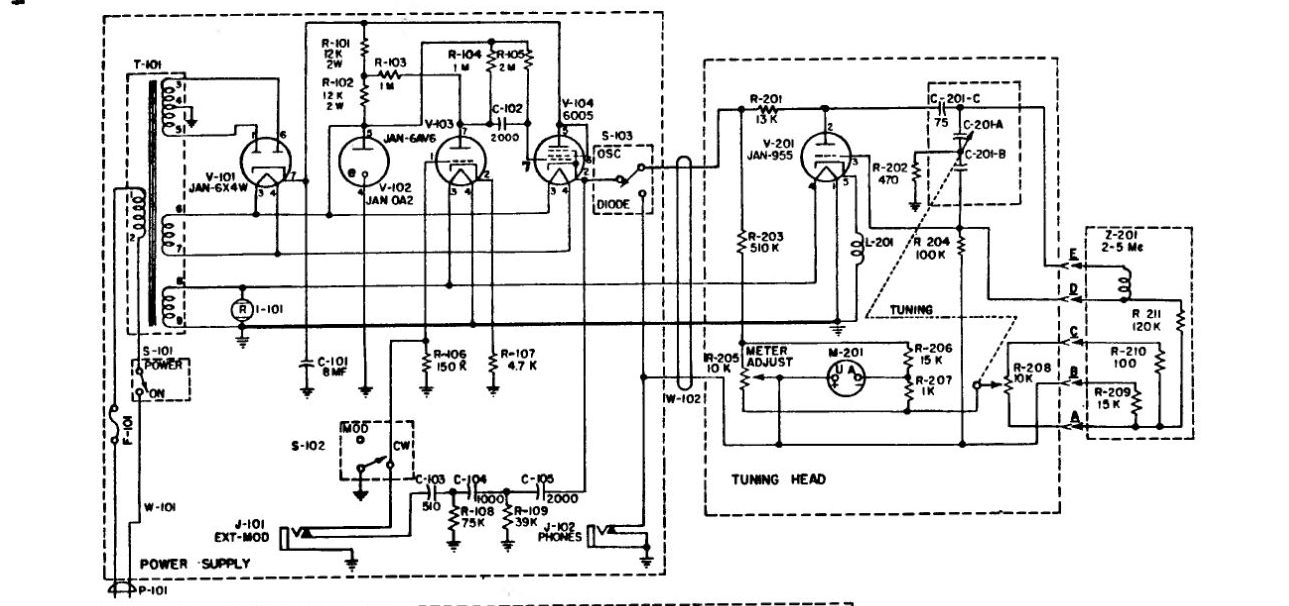
- As most commercial grid dip meters produced in the past, this one possesses several functions in addition to the grid dip function.
- One of these is the "absorption type wavemeter", that allows to measure the frequency of an incoming signal.
- Here is what they say in the doc:
- 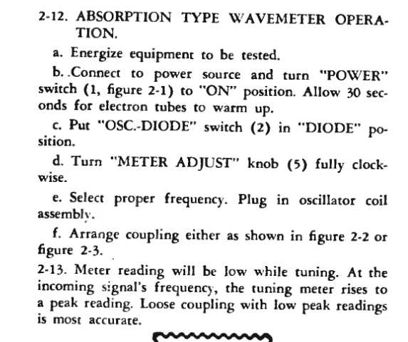
- I'm interested only in the tuning head part (the right box in the above schematic).
- In fact, I am only interested in understanding the "absorption wavemeter" function, that is, whenever switch S-103 is in diode position (the grid dip function is easier to understand and is not the subject here).
- Basically, the electron tube acts as a diode, which together with the network formed by the Z-201 coil and the tuning cap, forms a basic resonating detector. But I don't understand how the current flows and how this works.
- two important points that took me a while to understand:
- 1. in diode position, switch S-103 connects the top wire to the earphone jack, which is in fact a connection to ground: only when the earphone is plugged in, the jack disconnects from ground (by mechanical pressure) and then connects to the the 4k earphone impedance. Anyway, the earphone is not needed for the normal absorption wavemeter function: only micro ammeter M-201 is used.
- So, basically the top wire is connected to ground and is not powered. Only the filament of the electron tube is powered.
- 2. I was told that the grid of the electron tube is able to self biase (to a negative potential) whenever the filament of the tube is warmed.
- N.B: The whole documentation of the grid dip can be found [Here.](https://books.google.co.il/books/about/Operator_s_Manual.html?id=94U-AAAAYAAJ&redir_esc=y)
- Here is a [video](https://youtu.be/x0S2EgMU4s8) of the AN/PRM10, and
- here is a schematic (I believe the image can be zoomed):
- 
- As most commercial grid dip meters produced in the past, this one possesses several functions in addition to the grid dip function.
- One of these is the "absorption type wavemeter", that allows to measure the frequency of an incoming signal.
- Here is what they say in the doc:
- 
- I'm interested only in the tuning head part (the right box in the above schematic).
- In fact, I am only interested in understanding the "absorption wavemeter" function, that is, whenever switch S-103 is in diode position (the grid dip function is easier to understand and is not the subject here).
- Basically, the electron tube acts as a diode, which together with the network formed by the Z-201 coil and the tuning cap, forms a basic resonating detector. But I don't understand how the current flows and how this works.
- two important points that took me a while to understand:
- 1. in diode position, switch S-103 connects the top wire to the earphone jack, which is in fact a connection to ground: only when the earphone is plugged in, the jack disconnects from ground (by mechanical pressure) and then connects to the the 4k earphone impedance. Anyway, the earphone is not needed for the normal absorption wavemeter function: only micro ammeter M-201 is used.
- So, basically the top wire is connected to ground and is not powered. Only the filament of the electron tube is powered.
- 2. I was told that the grid of the electron tube is able to self biase (to a negative potential) whenever the filament of the tube is warmed.
- N.B: The whole documentation of the grid dip can be found [Here.](https://books.google.co.il/books/about/Operator_s_Manual.html?id=94U-AAAAYAAJ&redir_esc=y)
#6: Post edited
by
coquelicot
·
2021-02-21T19:22:46Z (over 4 years ago)
Here is a schematic of my AN/PRM10 grid dip (I believe the image can be zoomed):- 
I'm interested only in the tuning head part (the right box).In fact, I am only interested in understanding the "absorption wave" function, that is, whenever switch S-103 is in diode position (the grid dip function is easier to understand).- Basically, the electron tube acts as a diode, which together with the network formed by the Z-201 coil and the tuning cap, forms a basic resonating detector. But I don't understand how the current flows and how this works.
- two important points that took me a while to understand:
1. in diode position, switch S-103 connects the top wire to the microphone jack, which is in fact a connection to ground: only when the microphone is plugged in, the jack disconnects from ground (by mechanical pressure) and then connects to the the 4k microphone impedance. Anyway, the microphone is not needed for the normal absorption wave function: only micro ammeter M-201 is used.- So, basically the top wire is connected to ground and is not powered. Only the filament of the electron tube is powered.
- 2. I was told that the grid of the electron tube is able to self biase (to a negative potential) whenever the filament of the tube is warmed.
- N.B: The whole documentation of the grid dip can be found [Here.](https://books.google.co.il/books/about/Operator_s_Manual.html?id=94U-AAAAYAAJ&redir_esc=y)
- Here is a [video](https://youtu.be/x0S2EgMU4s8) of my AN/PRM10, and
- here is a schematic (I believe the image can be zoomed):
- 
- As most commercial grid dip meters produced in the past, this one possesses several functions in addition to the grid dip function.
- One of these is the "absorption type wavemeter", that allows to measure the frequency of an incoming signal.
- Here is what they say in the doc:
- 
- I'm interested only in the tuning head part (the right box in the above schematic).
- In fact, I am only interested in understanding the "absorption wavemeter" function, that is, whenever switch S-103 is in diode position (the grid dip function is easier to understand and is not the subject here).
- Basically, the electron tube acts as a diode, which together with the network formed by the Z-201 coil and the tuning cap, forms a basic resonating detector. But I don't understand how the current flows and how this works.
- two important points that took me a while to understand:
- 1. in diode position, switch S-103 connects the top wire to the earphone jack, which is in fact a connection to ground: only when the earphone is plugged in, the jack disconnects from ground (by mechanical pressure) and then connects to the the 4k earphone impedance. Anyway, the earphone is not needed for the normal absorption wavemeter function: only micro ammeter M-201 is used.
- So, basically the top wire is connected to ground and is not powered. Only the filament of the electron tube is powered.
- 2. I was told that the grid of the electron tube is able to self biase (to a negative potential) whenever the filament of the tube is warmed.
- N.B: The whole documentation of the grid dip can be found [Here.](https://books.google.co.il/books/about/Operator_s_Manual.html?id=94U-AAAAYAAJ&redir_esc=y)
#5: Post edited
by
coquelicot
·
2021-02-21T05:04:10Z (over 4 years ago)
- Here is a schematic of my AN/PRM10 grid dip (I believe the image can be zoomed):
- 
- I'm interested only in the tuning head part (the right box).
- In fact, I am only interested in understanding the "absorption wave" function, that is, whenever switch S-103 is in diode position (the grid dip function is easier to understand).
- Basically, the electron tube acts as a diode, which together with the network formed by the Z-201 coil and the tuning cap, forms a basic resonating detector. But I don't understand how the current flows and how this works.
- two important points that took me a while to understand:
- 1. in diode position, switch S-103 connects the top wire to the microphone jack, which is in fact a connection to ground: only when the microphone is plugged in, the jack disconnects from ground (by mechanical pressure) and then connects to the the 4k microphone impedance. Anyway, the microphone is not needed for the normal absorption wave function: only micro ammeter M-201 is used.
- So, basically the top wire is connected to ground and is not powered. Only the filament of the electron tube is powered.
2. I was told that the grid of the electron tube is able to self biase (to a negative potential) whenever the filament of the tube is warmed.
- Here is a schematic of my AN/PRM10 grid dip (I believe the image can be zoomed):
- 
- I'm interested only in the tuning head part (the right box).
- In fact, I am only interested in understanding the "absorption wave" function, that is, whenever switch S-103 is in diode position (the grid dip function is easier to understand).
- Basically, the electron tube acts as a diode, which together with the network formed by the Z-201 coil and the tuning cap, forms a basic resonating detector. But I don't understand how the current flows and how this works.
- two important points that took me a while to understand:
- 1. in diode position, switch S-103 connects the top wire to the microphone jack, which is in fact a connection to ground: only when the microphone is plugged in, the jack disconnects from ground (by mechanical pressure) and then connects to the the 4k microphone impedance. Anyway, the microphone is not needed for the normal absorption wave function: only micro ammeter M-201 is used.
- So, basically the top wire is connected to ground and is not powered. Only the filament of the electron tube is powered.
- 2. I was told that the grid of the electron tube is able to self biase (to a negative potential) whenever the filament of the tube is warmed.
- N.B: The whole documentation of the grid dip can be found [Here.](https://books.google.co.il/books/about/Operator_s_Manual.html?id=94U-AAAAYAAJ&redir_esc=y)
#4: Post edited
by
coquelicot
·
2021-02-20T20:12:26Z (over 4 years ago)
- Here is a schematic of my AN/PRM10 grid dip (I believe the image can be zoomed):
- 
- I'm interested only in the tuning head part (the right box).
- In fact, I am only interested in understanding the "absorption wave" function, that is, whenever switch S-103 is in diode position (the grid dip function is easier to understand).
- Basically, the electron tube acts as a diode, which together with the network formed by the Z-201 coil and the tuning cap, forms a basic resonating detector. But I don't understand how the current flows and how this works.
- two important points that took me a while to understand:
1. in diode position, switch S-103 connects the top wire to the microphone fixture, which is in fact a connection to ground: only when the microphone is plugged in, the fixture disconnects from ground (by mechanical pressure) and then connects to the the 4k microphone impedance. Anyway, the microphone is not needed for the normal absorption wave function: only micro ammeter M-201 is used.- So, basically the top wire is connected to ground and is not powered. Only the filament of the electron tube is powered.
- 2. I was told that the grid of the electron tube is able to self biase (to a negative potential) whenever the filament of the tube is warmed.
- Here is a schematic of my AN/PRM10 grid dip (I believe the image can be zoomed):
- 
- I'm interested only in the tuning head part (the right box).
- In fact, I am only interested in understanding the "absorption wave" function, that is, whenever switch S-103 is in diode position (the grid dip function is easier to understand).
- Basically, the electron tube acts as a diode, which together with the network formed by the Z-201 coil and the tuning cap, forms a basic resonating detector. But I don't understand how the current flows and how this works.
- two important points that took me a while to understand:
- 1. in diode position, switch S-103 connects the top wire to the microphone jack, which is in fact a connection to ground: only when the microphone is plugged in, the jack disconnects from ground (by mechanical pressure) and then connects to the the 4k microphone impedance. Anyway, the microphone is not needed for the normal absorption wave function: only micro ammeter M-201 is used.
- So, basically the top wire is connected to ground and is not powered. Only the filament of the electron tube is powered.
- 2. I was told that the grid of the electron tube is able to self biase (to a negative potential) whenever the filament of the tube is warmed.
#3: Post edited
by
coquelicot
·
2021-02-20T18:40:40Z (over 4 years ago)
- Here is a schematic of my AN/PRM10 grid dip (I believe the image can be zoomed):
- 
- I'm interested only in the tuning head part (the right box).
- In fact, I am only interested in understanding the "absorption wave" function, that is, whenever switch S-103 is in diode position (the grid dip function is easier to understand).
- Basically, the electron tube acts as a diode, which together with the network formed by the Z-201 coil and the tuning cap, forms a basic resonating detector. But I don't understand how the current flows and how this works.
- two important points that took me a while to understand:
1. in diode position, switch S-103 connects the top wire to the microphone fixture, which is in fact a connection to ground: only when the microphone is plugged in, the fixture disconnects from ground (by mechanical pressure) and then connects to the the 4k microphone impedance. Anyway, the microphone is not needed for the normal absorption wave function: only the micro ammeter is used.- So, basically the top wire is connected to ground and is not powered. Only the filament of the electron tube is powered.
- 2. I was told that the grid of the electron tube is able to self biase (to a negative potential) whenever the filament of the tube is warmed.
- Here is a schematic of my AN/PRM10 grid dip (I believe the image can be zoomed):
- 
- I'm interested only in the tuning head part (the right box).
- In fact, I am only interested in understanding the "absorption wave" function, that is, whenever switch S-103 is in diode position (the grid dip function is easier to understand).
- Basically, the electron tube acts as a diode, which together with the network formed by the Z-201 coil and the tuning cap, forms a basic resonating detector. But I don't understand how the current flows and how this works.
- two important points that took me a while to understand:
- 1. in diode position, switch S-103 connects the top wire to the microphone fixture, which is in fact a connection to ground: only when the microphone is plugged in, the fixture disconnects from ground (by mechanical pressure) and then connects to the the 4k microphone impedance. Anyway, the microphone is not needed for the normal absorption wave function: only micro ammeter M-201 is used.
- So, basically the top wire is connected to ground and is not powered. Only the filament of the electron tube is powered.
- 2. I was told that the grid of the electron tube is able to self biase (to a negative potential) whenever the filament of the tube is warmed.
#2: Post edited
by
coquelicot
·
2021-02-20T18:27:49Z (over 4 years ago)
- Here is a schematic of my AN/PRM10 grid dip (I believe the image can be zoomed):
- 
- I'm interested only in the tuning head part (the right box).
In fact, I am only interested in understanding the "absorption wave" function, that is, whenever switch S-103 is in diode position (the grid dip function is easiest to understand).- Basically, the electron tube acts as a diode, which together with the network formed by the Z-201 coil and the tuning cap, forms a basic resonating detector. But I don't understand how the current flows and how this works.
- two important points that took me a while to understand:
- 1. in diode position, switch S-103 connects the top wire to the microphone fixture, which is in fact a connection to ground: only when the microphone is plugged in, the fixture disconnects from ground (by mechanical pressure) and then connects to the the 4k microphone impedance. Anyway, the microphone is not needed for the normal absorption wave function: only the micro ammeter is used.
- So, basically the top wire is connected to ground and is not powered. Only the filament of the electron tube is powered.
- 2. I was told that the grid of the electron tube is able to self biase (to a negative potential) whenever the filament of the tube is warmed.
- Here is a schematic of my AN/PRM10 grid dip (I believe the image can be zoomed):
- 
- I'm interested only in the tuning head part (the right box).
- In fact, I am only interested in understanding the "absorption wave" function, that is, whenever switch S-103 is in diode position (the grid dip function is easier to understand).
- Basically, the electron tube acts as a diode, which together with the network formed by the Z-201 coil and the tuning cap, forms a basic resonating detector. But I don't understand how the current flows and how this works.
- two important points that took me a while to understand:
- 1. in diode position, switch S-103 connects the top wire to the microphone fixture, which is in fact a connection to ground: only when the microphone is plugged in, the fixture disconnects from ground (by mechanical pressure) and then connects to the the 4k microphone impedance. Anyway, the microphone is not needed for the normal absorption wave function: only the micro ammeter is used.
- So, basically the top wire is connected to ground and is not powered. Only the filament of the electron tube is powered.
- 2. I was told that the grid of the electron tube is able to self biase (to a negative potential) whenever the filament of the tube is warmed.
#1: Initial revision
by
coquelicot
·
2021-02-20T18:26:51Z (over 4 years ago)
My grid dip: how does this electron tube technology work?
Here is a schematic of my AN/PRM10 grid dip (I believe the image can be zoomed):  I'm interested only in the tuning head part (the right box). In fact, I am only interested in understanding the "absorption wave" function, that is, whenever switch S-103 is in diode position (the grid dip function is easiest to understand). Basically, the electron tube acts as a diode, which together with the network formed by the Z-201 coil and the tuning cap, forms a basic resonating detector. But I don't understand how the current flows and how this works. two important points that took me a while to understand: 1. in diode position, switch S-103 connects the top wire to the microphone fixture, which is in fact a connection to ground: only when the microphone is plugged in, the fixture disconnects from ground (by mechanical pressure) and then connects to the the 4k microphone impedance. Anyway, the microphone is not needed for the normal absorption wave function: only the micro ammeter is used. So, basically the top wire is connected to ground and is not powered. Only the filament of the electron tube is powered. 2. I was told that the grid of the electron tube is able to self biase (to a negative potential) whenever the filament of the tube is warmed.