Post History
UPDATED. based on clarification to original question. To be clear, just an idea, not tested for this situation! It is abusing the V_I_L margin on the 3.3V CMOS input, so series diode should be sc...
#20: Post edited
by
 Pete W
·
2021-02-24T00:30:01Z (over 4 years ago)
Pete W
·
2021-02-24T00:30:01Z (over 4 years ago)
- UPDATED. based on clarification to original question.
- To be clear, just an idea, not tested for this situation!
- 
- UPDATED. based on clarification to original question.
- To be clear, just an idea, not tested for this situation!
- It is abusing the V_I_L margin on the 3.3V CMOS input, so series diode should be schottky...
- 
#19: Post edited
by
Pete W
·
2021-02-23T23:55:59Z (over 4 years ago)
The optoisolator is nice if you want the grounds to also be isolated. Depending on what you are protecting against, here is a minimal resistor/diode based ideaIt just protects SIG1 > Vcc1. It could be protected from ESD up front with an additional bidirectional ESD diode, but SIG1 going excessively negative is an issue.- --------
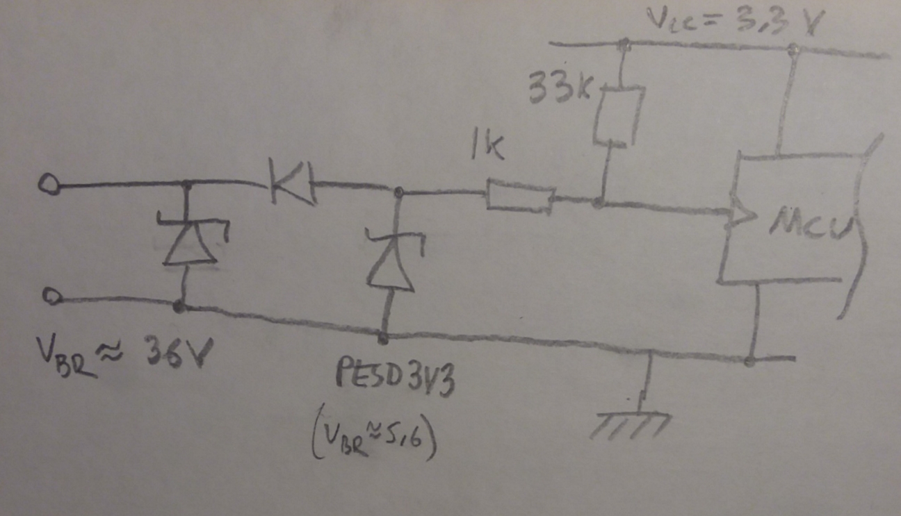
UPDATE, (to be clear, just an idea, not tested for this situation!) based on clarification to original question. Similar to Lundin's answer."Active low", as before. Should withstand accidental continuous +32V without hurting anything, around 34K seen at input in normal operation. The series diode cuts into the margin vs the CMOS input on the MCU, if it is an issue add a buffer with a higher V_I_L. The bidirectional 36V TVS might be reduntant for a negative transient.
- UPDATED. based on clarification to original question.
- To be clear, just an idea, not tested for this situation!
- 
- --------
#18: Post edited
by
Pete W
·
2021-02-23T23:51:12Z (over 4 years ago)
- The optoisolator is nice if you want the grounds to also be isolated. Depending on what you are protecting against, here is a minimal resistor/diode based idea
- 
- It just protects SIG1 > Vcc1. It could be protected from ESD up front with an additional bidirectional ESD diode, but SIG1 going excessively negative is an issue.
- -------
- UPDATE, (to be clear, just an idea, not tested for this situation!) based on clarification to original question. Similar to Lundin's answer.
"Active low", as before. Should withstand accidental continuous +32V without hurting anything, around 34K seen at input in normal operation. The series diode cuts into the margin vs the CMOS input on the MCU, if it is an issue add a buffer with a higher V_I_L. The bidirectional 36V TVS might be reduntant, could be unidirectional too, isn't going to save the other diode from a long -ve voltage. The 3V3 diode could arguably be moved behind the 1K...- 
- The optoisolator is nice if you want the grounds to also be isolated. Depending on what you are protecting against, here is a minimal resistor/diode based idea
- 
- It just protects SIG1 > Vcc1. It could be protected from ESD up front with an additional bidirectional ESD diode, but SIG1 going excessively negative is an issue.
- -------
- UPDATE, (to be clear, just an idea, not tested for this situation!) based on clarification to original question. Similar to Lundin's answer.
- "Active low", as before. Should withstand accidental continuous +32V without hurting anything, around 34K seen at input in normal operation. The series diode cuts into the margin vs the CMOS input on the MCU, if it is an issue add a buffer with a higher V_I_L. The bidirectional 36V TVS might be reduntant for a negative transient.
- 
#17: Post edited
by
Pete W
·
2021-02-23T23:49:07Z (over 4 years ago)
- The optoisolator is nice if you want the grounds to also be isolated. Depending on what you are protecting against, here is a minimal resistor/diode based idea
- 
- It just protects SIG1 > Vcc1. It could be protected from ESD up front with an additional bidirectional ESD diode, but SIG1 going excessively negative is an issue.
- -------
- UPDATE, (to be clear, just an idea, not tested for this situation!) based on clarification to original question. Similar to Lundin's answer.
"Active low", as before. Should withstand accidental continuous +32V without hurting anything, around 34K seen at input in normal operation. The series diode cuts into the margin vs the CMOS input on the MCU, if it is an issue add a buffer with a higher V_I_L. The bidirectional 36V TVS might be reduntant, could be unidirectional too, isn't going to save the other diode from a long -ve voltage.- 
- The optoisolator is nice if you want the grounds to also be isolated. Depending on what you are protecting against, here is a minimal resistor/diode based idea
- 
- It just protects SIG1 > Vcc1. It could be protected from ESD up front with an additional bidirectional ESD diode, but SIG1 going excessively negative is an issue.
- -------
- UPDATE, (to be clear, just an idea, not tested for this situation!) based on clarification to original question. Similar to Lundin's answer.
- "Active low", as before. Should withstand accidental continuous +32V without hurting anything, around 34K seen at input in normal operation. The series diode cuts into the margin vs the CMOS input on the MCU, if it is an issue add a buffer with a higher V_I_L. The bidirectional 36V TVS might be reduntant, could be unidirectional too, isn't going to save the other diode from a long -ve voltage. The 3V3 diode could arguably be moved behind the 1K...
- 
#16: Post edited
by
Pete W
·
2021-02-23T23:48:05Z (over 4 years ago)
- The optoisolator is nice if you want the grounds to also be isolated. Depending on what you are protecting against, here is a minimal resistor/diode based idea
- 
- It just protects SIG1 > Vcc1. It could be protected from ESD up front with an additional bidirectional ESD diode, but SIG1 going excessively negative is an issue.
- -------
UPDATE, based on clarification to original question. Similar to Lundin's answer.- "Active low", as before. Should withstand accidental continuous +32V without hurting anything, around 34K seen at input in normal operation. The series diode cuts into the margin vs the CMOS input on the MCU, if it is an issue add a buffer with a higher V_I_L. The bidirectional 36V TVS might be reduntant, could be unidirectional too, isn't going to save the other diode from a long -ve voltage.
- 
- The optoisolator is nice if you want the grounds to also be isolated. Depending on what you are protecting against, here is a minimal resistor/diode based idea
- 
- It just protects SIG1 > Vcc1. It could be protected from ESD up front with an additional bidirectional ESD diode, but SIG1 going excessively negative is an issue.
- -------
- UPDATE, (to be clear, just an idea, not tested for this situation!) based on clarification to original question. Similar to Lundin's answer.
- "Active low", as before. Should withstand accidental continuous +32V without hurting anything, around 34K seen at input in normal operation. The series diode cuts into the margin vs the CMOS input on the MCU, if it is an issue add a buffer with a higher V_I_L. The bidirectional 36V TVS might be reduntant, could be unidirectional too, isn't going to save the other diode from a long -ve voltage.
- 
#15: Post edited
by
Pete W
·
2021-02-23T23:46:28Z (over 4 years ago)
- The optoisolator is nice if you want the grounds to also be isolated. Depending on what you are protecting against, here is a minimal resistor/diode based idea
- 
- It just protects SIG1 > Vcc1. It could be protected from ESD up front with an additional bidirectional ESD diode, but SIG1 going excessively negative is an issue.
- -------
- UPDATE, based on clarification to original question. Similar to Lundin's answer.
"Active low", as before. Should withstand accidental continuous +32V without hurting anything, around 34K seen at input in normal operation. The series diode cuts into the margin vs the CMOS input on the MCU, if it is an issue add a buffer with a higher V_I_L. The 36V TVS could be unidirectional too, isn't going to save the other diode from a -ve voltage.- 
- The optoisolator is nice if you want the grounds to also be isolated. Depending on what you are protecting against, here is a minimal resistor/diode based idea
- 
- It just protects SIG1 > Vcc1. It could be protected from ESD up front with an additional bidirectional ESD diode, but SIG1 going excessively negative is an issue.
- -------
- UPDATE, based on clarification to original question. Similar to Lundin's answer.
- "Active low", as before. Should withstand accidental continuous +32V without hurting anything, around 34K seen at input in normal operation. The series diode cuts into the margin vs the CMOS input on the MCU, if it is an issue add a buffer with a higher V_I_L. The bidirectional 36V TVS might be reduntant, could be unidirectional too, isn't going to save the other diode from a long -ve voltage.
- 
#14: Post edited
by
Pete W
·
2021-02-23T23:43:58Z (over 4 years ago)
- The optoisolator is nice if you want the grounds to also be isolated. Depending on what you are protecting against, here is a minimal resistor/diode based idea
- 
- It just protects SIG1 > Vcc1. It could be protected from ESD up front with an additional bidirectional ESD diode, but SIG1 going excessively negative is an issue.
- -------
- UPDATE, based on clarification to original question. Similar to Lundin's answer.
"Active low", as before. Should withstand accidental continuous +32V without hurting anything, around 34K seen at input in normal operation. The series diode cuts into the margin vs the CMOS input on the MCU, if it is an issue add a buffer with a higher V_I_L.- 
- The optoisolator is nice if you want the grounds to also be isolated. Depending on what you are protecting against, here is a minimal resistor/diode based idea
- 
- It just protects SIG1 > Vcc1. It could be protected from ESD up front with an additional bidirectional ESD diode, but SIG1 going excessively negative is an issue.
- -------
- UPDATE, based on clarification to original question. Similar to Lundin's answer.
- "Active low", as before. Should withstand accidental continuous +32V without hurting anything, around 34K seen at input in normal operation. The series diode cuts into the margin vs the CMOS input on the MCU, if it is an issue add a buffer with a higher V_I_L. The 36V TVS could be unidirectional too, isn't going to save the other diode from a -ve voltage.
- 
#13: Post edited
by
Pete W
·
2021-02-23T23:38:49Z (over 4 years ago)
- The optoisolator is nice if you want the grounds to also be isolated. Depending on what you are protecting against, here is a minimal resistor/diode based idea
- 
- It just protects SIG1 > Vcc1. It could be protected from ESD up front with an additional bidirectional ESD diode, but SIG1 going excessively negative is an issue.
- -------
- UPDATE, based on clarification to original question. Similar to Lundin's answer.
"Active low", as before. Should withstand accidental continuous +32V without hurting anything, around 34K seen at input in normal operation. The series diode cuts into the margin vs the CMOS input on the MCU, if it is an issue add a buffer of some kind.- 
- The optoisolator is nice if you want the grounds to also be isolated. Depending on what you are protecting against, here is a minimal resistor/diode based idea
- 
- It just protects SIG1 > Vcc1. It could be protected from ESD up front with an additional bidirectional ESD diode, but SIG1 going excessively negative is an issue.
- -------
- UPDATE, based on clarification to original question. Similar to Lundin's answer.
- "Active low", as before. Should withstand accidental continuous +32V without hurting anything, around 34K seen at input in normal operation. The series diode cuts into the margin vs the CMOS input on the MCU, if it is an issue add a buffer with a higher V_I_L.
- 
#12: Post edited
by
Pete W
·
2021-02-23T23:32:52Z (over 4 years ago)
- The optoisolator is nice if you want the grounds to also be isolated. Depending on what you are protecting against, here is a minimal resistor/diode based idea
- 
- It just protects SIG1 > Vcc1. It could be protected from ESD up front with an additional bidirectional ESD diode, but SIG1 going excessively negative is an issue.
- -------
- UPDATE, based on clarification to original question. Similar to Lundin's answer.
"Active low", as before. Should withstand accidental continuous +32V, around 34K seen at input in normal operation. The series diode cuts into the margin vs the CMOS input on the MCU, if it is an issue add a buffer of some kind.- 
- The optoisolator is nice if you want the grounds to also be isolated. Depending on what you are protecting against, here is a minimal resistor/diode based idea
- 
- It just protects SIG1 > Vcc1. It could be protected from ESD up front with an additional bidirectional ESD diode, but SIG1 going excessively negative is an issue.
- -------
- UPDATE, based on clarification to original question. Similar to Lundin's answer.
- "Active low", as before. Should withstand accidental continuous +32V without hurting anything, around 34K seen at input in normal operation. The series diode cuts into the margin vs the CMOS input on the MCU, if it is an issue add a buffer of some kind.
- 
#11: Post edited
by
Pete W
·
2021-02-23T23:32:01Z (over 4 years ago)
- The optoisolator is nice if you want the grounds to also be isolated. Depending on what you are protecting against, here is a minimal resistor/diode based idea
- 
- It just protects SIG1 > Vcc1. It could be protected from ESD up front with an additional bidirectional ESD diode, but SIG1 going excessively negative is an issue.
- -------
- UPDATE, based on clarification to original question. Similar to Lundin's answer.
"Active low", protects input, should withstand accidental continuous +32V, around 34K seen at input in normal operation. The series diode cuts into the margin vs the CMOS input on the MCU, if it is an issue add a buffer of some kind.- 
- The optoisolator is nice if you want the grounds to also be isolated. Depending on what you are protecting against, here is a minimal resistor/diode based idea
- 
- It just protects SIG1 > Vcc1. It could be protected from ESD up front with an additional bidirectional ESD diode, but SIG1 going excessively negative is an issue.
- -------
- UPDATE, based on clarification to original question. Similar to Lundin's answer.
- "Active low", as before. Should withstand accidental continuous +32V, around 34K seen at input in normal operation. The series diode cuts into the margin vs the CMOS input on the MCU, if it is an issue add a buffer of some kind.
- 
#10: Post edited
by
Pete W
·
2021-02-23T23:31:22Z (over 4 years ago)
- The optoisolator is nice if you want the grounds to also be isolated. Depending on what you are protecting against, here is a minimal resistor/diode based idea
- 
- It just protects SIG1 > Vcc1. It could be protected from ESD up front with an additional bidirectional ESD diode, but SIG1 going excessively negative is an issue.
- -------
- UPDATE, based on clarification to original question. Similar to Lundin's answer.
"Active low", protects input, should withstand accidental continuous +32V, around 34K seen at input. The series diode cuts into the margin vs the CMOS input on the MCU, if it is an issue add a buffer of some kind.- 
- The optoisolator is nice if you want the grounds to also be isolated. Depending on what you are protecting against, here is a minimal resistor/diode based idea
- 
- It just protects SIG1 > Vcc1. It could be protected from ESD up front with an additional bidirectional ESD diode, but SIG1 going excessively negative is an issue.
- -------
- UPDATE, based on clarification to original question. Similar to Lundin's answer.
- "Active low", protects input, should withstand accidental continuous +32V, around 34K seen at input in normal operation. The series diode cuts into the margin vs the CMOS input on the MCU, if it is an issue add a buffer of some kind.
- 
#9: Post edited
by
Pete W
·
2021-02-23T23:28:52Z (over 4 years ago)
- The optoisolator is nice if you want the grounds to also be isolated. Depending on what you are protecting against, here is a minimal resistor/diode based idea
- 
- It just protects SIG1 > Vcc1. It could be protected from ESD up front with an additional bidirectional ESD diode, but SIG1 going excessively negative is an issue.
SIG1 would have to provide the full I_F for the opto's LED, which looks like 10mA recommended, quite a lot for an MCU output pin. A different opto with a lower I_F might make things a little easier.
- The optoisolator is nice if you want the grounds to also be isolated. Depending on what you are protecting against, here is a minimal resistor/diode based idea
- 
- It just protects SIG1 > Vcc1. It could be protected from ESD up front with an additional bidirectional ESD diode, but SIG1 going excessively negative is an issue.
- -------
- UPDATE, based on clarification to original question. Similar to Lundin's answer.
- "Active low", protects input, should withstand accidental continuous +32V, around 34K seen at input. The series diode cuts into the margin vs the CMOS input on the MCU, if it is an issue add a buffer of some kind.
- 
#8: Post edited
by
Pete W
·
2021-02-23T19:08:29Z (over 4 years ago)
- The optoisolator is nice if you want the grounds to also be isolated. Depending on what you are protecting against, here is a minimal resistor/diode based idea
- 
It just protects SIG1 > Vcc1. It could be protected from ESD up front with an additional bidirectional ESD diode, but SIG1 going excessively negative is an issue. It could be rearranged a little bit to move R1 next to SIG1, so that the path thru both diodes goes thru R1, but the dissipation in it at -32V would be no good.- SIG1 would have to provide the full I_F for the opto's LED, which looks like 10mA recommended, quite a lot for an MCU output pin. A different opto with a lower I_F might make things a little easier.
- The optoisolator is nice if you want the grounds to also be isolated. Depending on what you are protecting against, here is a minimal resistor/diode based idea
- 
- It just protects SIG1 > Vcc1. It could be protected from ESD up front with an additional bidirectional ESD diode, but SIG1 going excessively negative is an issue.
- SIG1 would have to provide the full I_F for the opto's LED, which looks like 10mA recommended, quite a lot for an MCU output pin. A different opto with a lower I_F might make things a little easier.
#7: Post edited
by
Pete W
·
2021-02-23T19:07:58Z (over 4 years ago)
- The optoisolator is nice if you want the grounds to also be isolated. Depending on what you are protecting against, here is a minimal resistor/diode based idea
- 
It just protects SIG1 > Vcc1. It could be protected from ESD up front with an additional bidirectional ESD diode, but SIG1 going excessively negative is an issue. It could be rearranged a little bit to move R1 next to SIG1, so that the path thru both diodes goes thru a resistor.- SIG1 would have to provide the full I_F for the opto's LED, which looks like 10mA recommended, quite a lot for an MCU output pin. A different opto with a lower I_F might make things a little easier.
- The optoisolator is nice if you want the grounds to also be isolated. Depending on what you are protecting against, here is a minimal resistor/diode based idea
- 
- It just protects SIG1 > Vcc1. It could be protected from ESD up front with an additional bidirectional ESD diode, but SIG1 going excessively negative is an issue. It could be rearranged a little bit to move R1 next to SIG1, so that the path thru both diodes goes thru R1, but the dissipation in it at -32V would be no good.
- SIG1 would have to provide the full I_F for the opto's LED, which looks like 10mA recommended, quite a lot for an MCU output pin. A different opto with a lower I_F might make things a little easier.
#6: Post edited
by
Pete W
·
2021-02-23T19:05:59Z (over 4 years ago)
- The optoisolator is nice if you want the grounds to also be isolated. Depending on what you are protecting against, here is a minimal resistor/diode based idea
- 
It just protects SIG1 > Vcc1. It could be protected from ESD up front with an additional bidirectional ESD diode, but SIG1 going excessively negative is an issue. It could possible be rearranged a little bit to move R1 next to SIG1, so that the path thru both diodes goes thru a resistor.- SIG1 would have to provide the full I_F for the opto's LED, which looks like 10mA recommended, quite a lot for an MCU output pin. A different opto with a lower I_F might make things a little easier.
- The optoisolator is nice if you want the grounds to also be isolated. Depending on what you are protecting against, here is a minimal resistor/diode based idea
- 
- It just protects SIG1 > Vcc1. It could be protected from ESD up front with an additional bidirectional ESD diode, but SIG1 going excessively negative is an issue. It could be rearranged a little bit to move R1 next to SIG1, so that the path thru both diodes goes thru a resistor.
- SIG1 would have to provide the full I_F for the opto's LED, which looks like 10mA recommended, quite a lot for an MCU output pin. A different opto with a lower I_F might make things a little easier.
#5: Post edited
by
Pete W
·
2021-02-23T19:05:27Z (over 4 years ago)
- The optoisolator is nice if you want the grounds to also be isolated. Depending on what you are protecting against, here is a minimal resistor/diode based idea
- 
It just protects SIG1 > Vcc1. It could be protected from ESD up front with an additional bidirectional ESD diode, but SIG1 going excessively negative is an issue. SIG1 would have to provide the full I_F for the opto's LED, which looks like 10mA recommended, quite a lot for an MCU output pin. A different opto with a lower I_F might make things a little easier.
- The optoisolator is nice if you want the grounds to also be isolated. Depending on what you are protecting against, here is a minimal resistor/diode based idea
- 
- It just protects SIG1 > Vcc1. It could be protected from ESD up front with an additional bidirectional ESD diode, but SIG1 going excessively negative is an issue. It could possible be rearranged a little bit to move R1 next to SIG1, so that the path thru both diodes goes thru a resistor.
- SIG1 would have to provide the full I_F for the opto's LED, which looks like 10mA recommended, quite a lot for an MCU output pin. A different opto with a lower I_F might make things a little easier.
#4: Post edited
by
Pete W
·
2021-02-23T19:03:09Z (over 4 years ago)
- The optoisolator is nice if you want the grounds to also be isolated. Depending on what you are protecting against, here is a minimal resistor/diode based idea
- 
It just protects SIG1 > Vcc1. It could be protected from ESD up front with an additional bidirectional ESD diode, but SIG1 going excessively negative is an issue. SIG1 would have to provide the full I_F for the opto's LED, which looks like 10mA recommended, quite a lot for an MCU output pin.
- The optoisolator is nice if you want the grounds to also be isolated. Depending on what you are protecting against, here is a minimal resistor/diode based idea
- 
- It just protects SIG1 > Vcc1. It could be protected from ESD up front with an additional bidirectional ESD diode, but SIG1 going excessively negative is an issue. SIG1 would have to provide the full I_F for the opto's LED, which looks like 10mA recommended, quite a lot for an MCU output pin. A different opto with a lower I_F might make things a little easier.
#3: Post edited
by
Pete W
·
2021-02-23T19:02:18Z (over 4 years ago)
- The optoisolator is nice if you want the grounds to also be isolated. Depending on what you are protecting against, here is a minimal resistor/diode based idea
- 
It just protects SIG1 > Vcc1. It could be protected from ESD up front, but SIG1 going excessively negative is an issue. SIG1 would have to provide the full I_F for the opto's LED, which looks like 10mA recommended, quite a lot for an MCU output pin.
- The optoisolator is nice if you want the grounds to also be isolated. Depending on what you are protecting against, here is a minimal resistor/diode based idea
- 
- It just protects SIG1 > Vcc1. It could be protected from ESD up front with an additional bidirectional ESD diode, but SIG1 going excessively negative is an issue. SIG1 would have to provide the full I_F for the opto's LED, which looks like 10mA recommended, quite a lot for an MCU output pin.
#2: Post edited
by
Pete W
·
2021-02-23T19:01:18Z (over 4 years ago)
The optoisolator is nice if you want the grounds to also be isolated. Depending on what you are protecting against, some resistor/diode based ideas:The first one with R1,R2,D3 just protects SIG1 > Vcc1. It could be protected from ESD up front, but SIG1 going excessively negative presents an issue.The second one adds R3, which in principle limits current when SIG1 is excessively negative. But at -32V, R3 would have to dissipate too much ... Example: R1=0, R2=330, R3=1K, dissipates 1W at -32V , so another approach would be needed if that condition happens for more than a very short time
- The optoisolator is nice if you want the grounds to also be isolated. Depending on what you are protecting against, here is a minimal resistor/diode based idea
- 
- It just protects SIG1 > Vcc1. It could be protected from ESD up front, but SIG1 going excessively negative is an issue. SIG1 would have to provide the full I_F for the opto's LED, which looks like 10mA recommended, quite a lot for an MCU output pin.
#1: Post edited
by
Pete W
·
2021-02-23T18:57:18Z (over 4 years ago)
- The optoisolator is nice if you want the grounds to also be isolated. Depending on what you are protecting against, some resistor/diode based ideas:
- 
- The first one with R1,R2,D3 just protects SIG1 > Vcc1. It could be protected from ESD up front, but SIG1 going excessively negative presents an issue.
The second one addr R3, in principle limits current when SIG1 is excessively negative. But R3 would have to dissipate too much at -32V ... Example: R1=0, R2=330, R3=1K, dissipates 1W at -32V , so another approach would be needed if that condition happens for more than a very short time
- The optoisolator is nice if you want the grounds to also be isolated. Depending on what you are protecting against, some resistor/diode based ideas:
- 
- The first one with R1,R2,D3 just protects SIG1 > Vcc1. It could be protected from ESD up front, but SIG1 going excessively negative presents an issue.
- The second one adds R3, which in principle limits current when SIG1 is excessively negative. But at -32V, R3 would have to dissipate too much ... Example: R1=0, R2=330, R3=1K, dissipates 1W at -32V , so another approach would be needed if that condition happens for more than a very short time