555 timer, PAM with digital signal
I'd like to use a 555 timer as carrier wave generator at ~ 50 kHz and modulate the amplitude with an external digital signal at ~ 1 kHz. The pulse width remains constant at 10us (50% duty cycle).
Do you suggest to add MOSFET on the OUT pin of 555 timer, or can I connect the signal directly to a pin of the 555 timer?
I saw here that the digital signal is plugged directly into the RESET pin. Does this have undesirable side effects, or is it a good practice?
Thanks!
1 answer
The 555 timer has a maximum output current rating (for example 250 mA for the NE555, check your 555 version datasheet). So whether or not you have to introduce a mosfet depends on whether your application is current demanding or not. For less than 100 mA (say), you can connect directly your 555 to whatever you intend to.
The link you provided leads to a non related document for me.
the digital signal is plugged directly into the RESET pin
what digital signal? if you want to modulate the carrier signal at the output of the 555, you can simply try to modulate the input voltage at the input supply current pin of the 555. That may work or not (I've not tried). Otherwise, you may want to use a npn transistor mounted as a switch (load above the collector) whose base is driven by the 555 output, and to modulate the input voltage of the "switch" at the desired frequency.
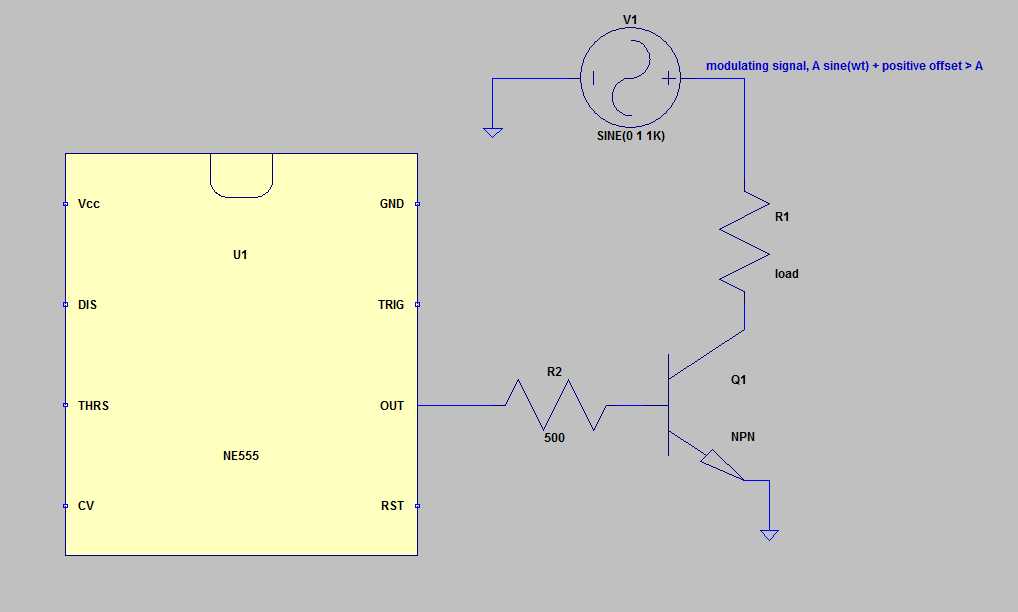
Note: the load above could be the primary of a transformer.
As Andy said, it is difficult to help whenever nothing is known about your application (do you have a positive and negative supply power?, do you need a modulated wave above ground or centered at ground?) etc.
Also, I hope you don't intend to use that for radio communication: at these very low frequencies, that will be difficult.
ADDED:
OK. Now that the problem of the link is fixed and I've read the document, I understand what you are trying to do.
The answer is "Yes", you can connect directly the output pin of the various 555 to the relevant parts, because the various datasheets specify a large maximum reset voltage and a small reset current of about 1mA. So, there is no problem with that. No need to use a mosfet for this application.
And yes, I think this is certainly not a "bad practice" to use the reset pin.

1 comment thread