Motor Controller - What might be the purpose of these resistors?
I was looking at the video of the Tesla Model 3 motor controller(400VDC, 500A) disassembly and noticed a resistor network as in the picture below. They are 2k resistors(SMD code 202).
See the picture below:
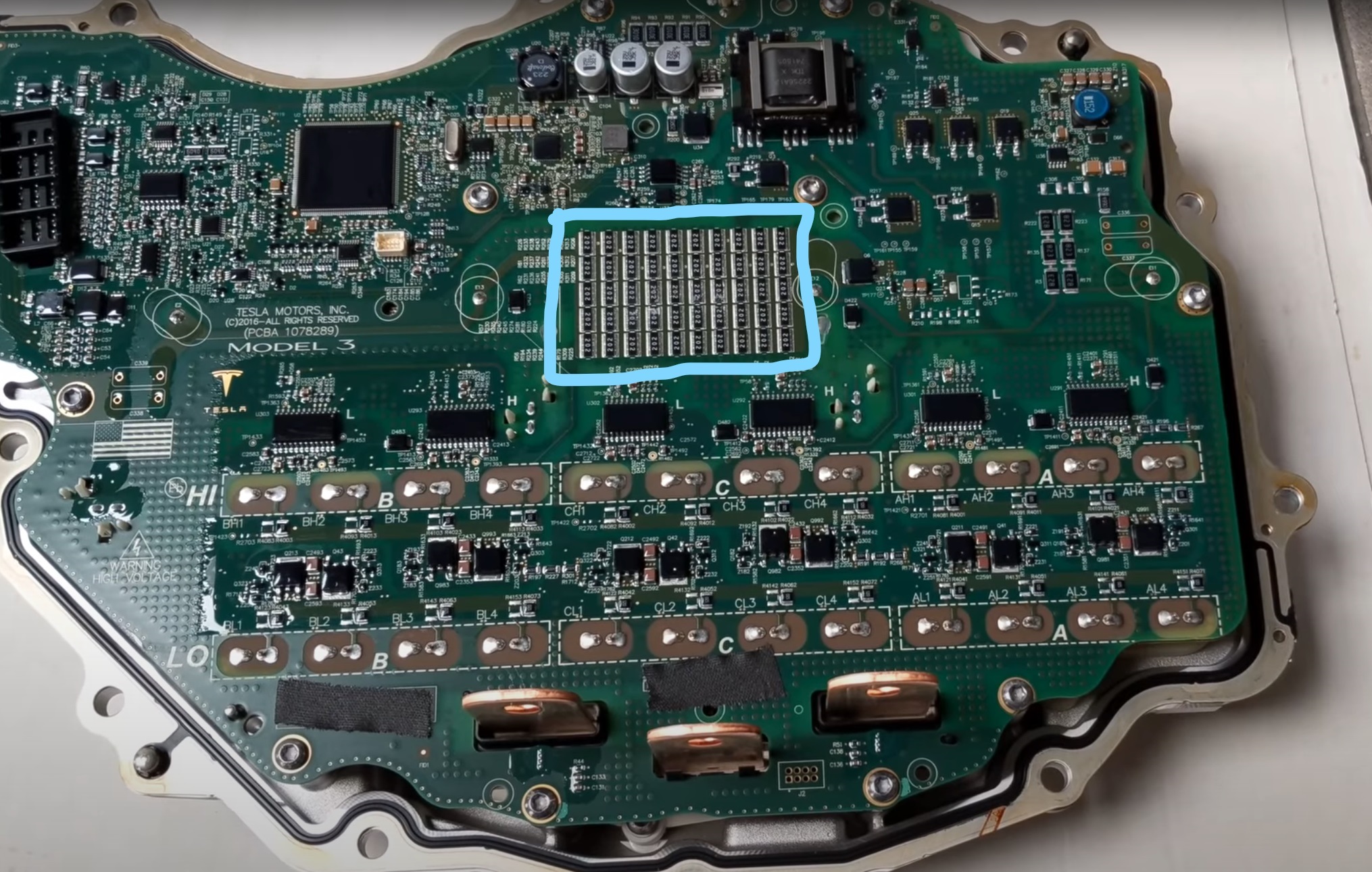
I was wondering what might be the reason for putting these resistors in a motor controller unit?
Some of the reasons I have been thinking of:
- Bleeding resistors for the input bulk capacitance when the controller is disconnected from the main battery
- Dissipative brake when the motor is acting as a generator in order to mitigate the overvoltage on the bus.
Here is the video if you are interested video link - I've linked the part where resistors are zoomed in.
4 answers
You are accessing this answer with a direct link, so it's being shown above all other answers regardless of its score. You can return to the normal view.
To expand on Olin's answer about power dissipation, one theory is EX/ATEX qualification for explosive environments. This is likely needed for these kind of cars, given the massive energy in those batteries.
For EX qualification you are not allowed to have a thermal peak somewhere on the board in case of faults. Film resistors are regarded as safe components, since they are expected to break like a fuse upon too high currents. But you'll want to spread the heat as evenly as possible across the board. Depending on what EX classification you are aiming for, there are different temperature requirements.
There's other places on the same board where they have grouped together several 2512. For EX you could add such very low ohm resistors in series with voltage regulators and other such components likely to give off a lot of heat in case of shorts somewhere.
This is just speculation, but the boards we made in an EX project I was involved in ended up with a lot of 2512 in weird places, seemingly nonsensical if you didn't know why they were placed there.
0 comment threads
Reasons this is sometimes done:
- To get higher power dissipation.
- To get higher voltage capability.
- To get lower parasitic capacitance.
For 1 and 2 the "normal" answer is to use a resistor rated for the required power or voltage in the first place. However, there are some advantages to using multiple smaller resistors. You don't have to stock another part, you can buy the smaller part in higher volume, and you can control how the heat is spread out.
#3 is because while the resistance of multiple resistors in series increases resistance, the parasitic capacitance decreases. For example, consider individual resistors that are 2 kΩ with 5 pF parasitic capacitance across them. Putting 5 of those in series yields 10 kΩ with 1 pF parasitic capacitance.
We can't tell what the engineers at Tesla had in mind here from just this picture. We can't even know what parallel/series combination those resistors are in. Perhaps each string of 5 resistors is one power resistor. Maybe it was convenient to have these power resistors long and thin.
Higher voltage capability is probably not the answer since the resistances are low. If those are 0805 packages, then ⅛ W is about the limit. That would be reached with only 16 V across each 2 kΩ resistor. 0805 resistors have considerably more voltage capability than that. Put another way, you could only put 80 V across a string of five resistors anyway. Unless this is for absorbing short high voltage transients, this is not the reason.
0 comment threads
I'd guess surge resistance and redundancy, rather than power dissipation.
Looks like 10 stages of 5x parallel 2k going left to right?? So that's 10x400 = 4k. Perhaps used for parallel damping the DC link???? (the 6 subcircuits below would be 3phase half bridges??). Presumably then the DC link would be prone to big inductive spikes (thus HV), as various diodes return to it.
If it were exclusively thermal / non-momentary power dissipation, I think the pads could have been made larger and/or more widely spread relative to the resistor package- not 100% sure this is always the case however.
0 comment threads


1 comment thread