CAN "split" pin, bus termination and common mode stabilization
Modern CAN transceivers like MCP2561FD that support CAN FD with high baudrates come with an optional feature called SPLIT, which is to my understanding a reference voltage output pin used to give a common mode stabilization and thereby reduce radiated emissions. It gives out 0.5Vdd so that would be the 2.5V idle voltage of CAN.
Example application from the above linked datasheet:
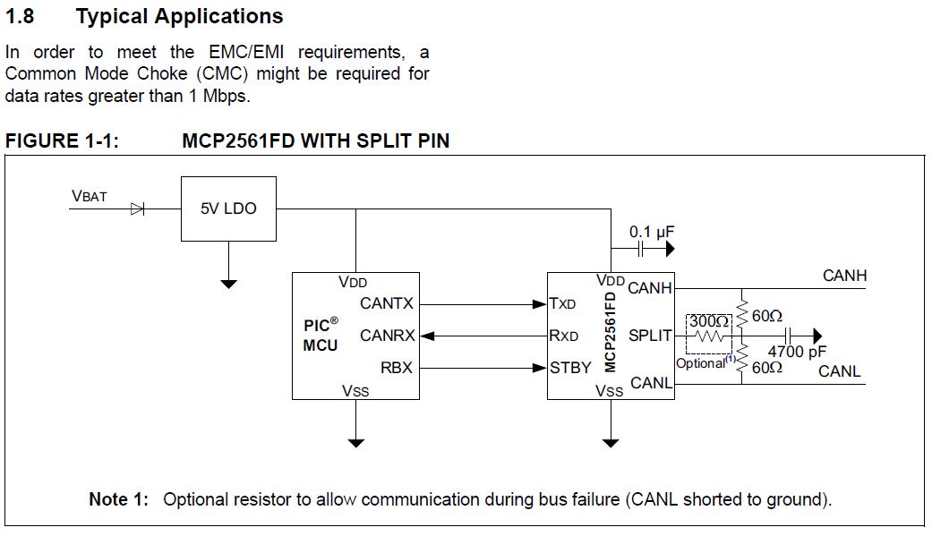
They don't show where the mentioned common mode choke should be placed. I've always used one and usually place it between the transceiver and the 120R terminating resistor.
But it would seem that they've placed the SPLIT pin at the centre of the terminating resistors? Can anyone explain the theory behind this pin and at what speeds it might become useful?
Am I correct in assuming the 60R + 60R are the terminating resistors? If so, what if the node is not the last one on the bus? How to connect this pin then? And where to place the common mode choke?
1 answer
Can anyone explain the theory behind this pin
You have already done so yourself:
used to give a common mode stabilization and thereby reduce radiated emissions
As far as I know, that is exactly the reason. Since the CANH/CANL lines are supposed to be a twisted pair, radiation comes from the common mode signal, not the differential.
Ideally, a voltage change in one line is always exactly matched by the opposite voltage change in the other line. However, in real life there is some error on that. I have looked at regular (1 Mb/s) CAN lines with a scope, and was surprised how much asymmetry there was. The differential signal was actually quite clean, but there were some bumps on the common mode signal.
The low speed CAN termination scheme only pulls the lines together. It does nothing to dissipate common mode excursions. By splitting the terminator and connecting the center to a fixed voltage, there is also some pull on the common mode signal towards that voltage.
at what speeds it might become useful?
It's not speed so much as edge rise and fall times. Of course the faster the signal, the faster the rise and fall times need to be, so there is some implicit speed dependency.
One way to get a feeling where the split terminator starts to matter is by looking at the low pass filter rolloff frequency. The common mode signal is tied to ground via 30 Ω and 4.7 nF in series. That comes out to 1.1 MHz, which is roughly where the split will start to make a difference in the circuit you show.
Keep in mind that even for slow CAN, there will be harmonics well past 1.1 MHz. Again, it's not about the bit rate as much as the edge rise and fall times. It's the sharp rise and falls that contain the high frequencies that cause radiation, and those are exactly the frequencies the split terminator will load in the common mode signal.
Am I correct in assuming the 60R + 60R are the terminating resistors?
Yes.
If so, what if the node is not the last one on the bus?
Then you can't add the terminators at all. This is not a perfect system for eliminating all common mode signal, but it still helps even with just the terminators at the ends of the bus.
And where to place the common mode choke?
I have not used this kind of CAN transceiver before, so have no first hand experience. My first reaction would be to place the common mode choke immediately adjacent to the bus driver. That's where any asymmetry originates, so that's the best place to attenuate it. The split terminators then also act as a load on the common mode signal. Remember that a common mode choke doesn't attenuate the common mode signal by itself, but only raises its impedance. It takes some load impedance following the choke to cause the actual attenuation.
I would also not want to add anything unnecessary between the transmission line terminators and other parts of the transmission line. No common mode choke is perfect, so there will be some disruption of the transmission line impedance.
0 comment threads

0 comment threads