MOSFET not turning completely off
Hello everyone,
I have a simple circuit in which I control some LEDs via an MCU and DMG2302UK ( N-channel MOSFET )

The EN pin is connected to an MCU gpio pin that works at 3.3V.
The circuit worked perfectly for some time, and suddenly the LED were always-on (very dim), there was some sort of leakage current, changing the resistor and the capacitor didn't help, it only worked again when the MOSFET was changed with a new one.
Note that the MOSFET was switching successfully as I can see the LEDs turning brighter when switched ON, but it just doesn't turn completely OFF
I imagine that something might have damaged the MOSFET but not sure what, the main thing I am thinking about is not connecting a resistor between the gate and the EN pin which might have damaged the MOSFET with time as per this page
What do you think might have damaged the MOSFET ? and how to enhance this circuit ?
Thank you
1 answer
To protect against future changes and to provide something slightly more readable, here is your schematic:
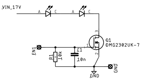
There is no immediately obvious reason the FET should blow, but there are a number of issues here:
- If "VIN_17V" is to be believed, and the voltage really is 17 V, then that is way too much for two LEDs of any kind in series. I would have expected the 17 V supply to sag or the LEDs to get fried before the FET, but you haven't given us the details of the LEDs.
The FET can safely pass a few amps. I would therefore not expect it to be the weak link in the chain. If the LEDs got fried and failed shorted, then I wouldn't expect them to light anymore.
In any case, you need something limiting the current to the least of what the LEDs, FET, and power supply can handle.
- What is the real input voltage? Is that maybe meant to be nominally 17 V? What is the maximum? Note that the FET can only withstand 20 V. If there is a chance that the input voltage can exceed 20 V, even for short glitches, then it's no surprise the FET got damaged.
- I can't even guess what you think C1 is doing for you. You say EN1 is driven by a microcontroller output pin. That should be actively holding EN1 at 3.3 V or 0 V for on and off, respectively. All C1 does is add a high current load on the micro output when it is trying to transition between the on and off states.
- Are you sure the grounds of the micro and the FET are connected? If the micro is essentially floating with respect to the FET, the gate-source limit of ±12 V max could easily be exceeded.
- Most likely something isn't as you say it is or think it is. Given the sloppiness of your schematic, we can only assume the same lack of attention to detail was applied to building and testing this circuit. I get the impression it would be pointless to go into details (ask a separate question if you really want to know), but I'm warning you that this level of disrespect won't be tolerated from you here in the future. Next time the question will be closed so that you have to clean it up before the system will let anyone answer.
the two LEDs are just symbolic, I didn't want to clutter the question with a bigger picture. ... I only took the part of the schematic I thought relevant.
That's not the way to do it. I realize when you don't know the answer to a question, it's not always obvious what's relevant and what isn't. Of course in this case of a FET blowing out, the load should have been considered as likely relevant.
However, the real problem was that you provided something definitive-looking that was actually quite different. By explicitly showing two LEDs, we can only assume you have two LEDs there. If you had drawn a box labeled "load", at least we would have known that we didn't know what the load was. That may have caused the question to be closed until that information was forthcoming, but several people wouldn't have wasted volunteer time trying to figure out what was going on with two LEDs as the load.
in total there are 10 LEDs split into two parallel branches and 1ohm current limiting resistors. ... The maximum current that should pass at 100% duty cycle is 2A.
This paints a completely different picture of your circuit.
However a 10% duty cycle was never exceeded
It would be good to know the PWM frequency, but I have a suspicion what is going on.
C1 is slowing down the gate switching edges. That causes the FET to spend significant time in the in-between region, between full on and full off. That causes significant power dissipation in the FET, which eventually heats it to destruction.
The solution is to make sure the switching transition time is a small fraction of the total time. This is done with a combination of fast switching transitions on the gate, and a low enough PWM frequency.
Absolutely get rid of C1! That slows down the switching edges, which may have ultimately caused the FET to fry. After ditching C1, take a look at the gate waveform on a scope and make sure it has fast edges, and flat levels at 0 V and 3.3 V. If not, there is more you're not telling us, which still needs to be fixed.
1 comment thread

1 comment thread