Post History
I am trying to analyse what is controlling the load current in the below Darlington configuration. Is it the base current of transistor Q3 which is controlling current through R14 / emitter curr...
#7: Post edited
by
 Lorenzo Donati
·
2023-08-09T20:39:27Z (almost 2 years ago)
Lorenzo Donati
·
2023-08-09T20:39:27Z (almost 2 years ago)
Retagged.
#6: Post edited
by
Lorenzo Donati
·
2023-07-28T15:38:08Z (almost 2 years ago)
Removed redundant tag.
#5: Post edited
by
 kadamrohan16
·
2022-02-04T15:24:24Z (over 3 years ago)
kadamrohan16
·
2022-02-04T15:24:24Z (over 3 years ago)
- I am trying to analyse what is controlling the load current in the below Darlington configuration.
- 1. Is it the base current of transistor Q3 which is controlling current through R14 / emitter current of Q2?
- 
- 2. If it is, then is the maximum permissible load current is calculated by Ic(Q3) * Q1 beta * Q2 beta ?
- 3. From light load to maximum load, will all three transistor stay in the active region? For light loads , Q2 may get into saturation region I suppose.
- EDIT :
Alternate circuit to acheive the same functionality- 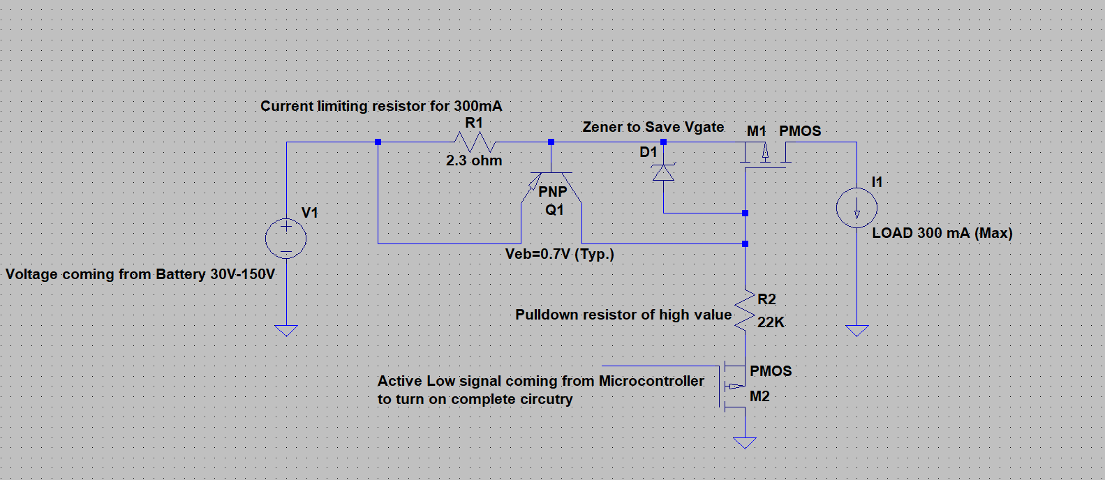
- are there any drawbacks to use this circuit ?
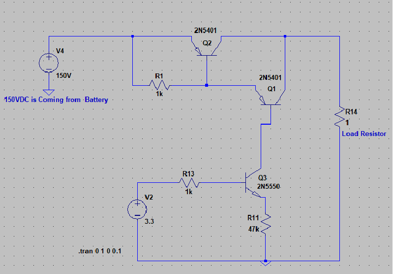
- I am trying to analyse what is controlling the load current in the below Darlington configuration.
- 1. Is it the base current of transistor Q3 which is controlling current through R14 / emitter current of Q2?
- 
- 2. If it is, then is the maximum permissible load current is calculated by Ic(Q3) * Q1 beta * Q2 beta ?
- 3. From light load to maximum load, will all three transistor stay in the active region? For light loads , Q2 may get into saturation region I suppose.
- EDIT :
- Alternate circuit to achieve the same functionality
- 
- are there any drawbacks to use this circuit ?
#4: Post edited
by
kadamrohan16
·
2022-02-04T15:23:48Z (over 3 years ago)
- I am trying to analyse what is controlling the load current in the below Darlington configuration.
- 1. Is it the base current of transistor Q3 which is controlling current through R14 / emitter current of Q2?
- 
- 2. If it is, then is the maximum permissible load current is calculated by Ic(Q3) * Q1 beta * Q2 beta ?
3. From light load to maximum load, will all three transistor stay in the active region? For light loads , Q2 may get into saturation region I suppose.
- I am trying to analyse what is controlling the load current in the below Darlington configuration.
- 1. Is it the base current of transistor Q3 which is controlling current through R14 / emitter current of Q2?
- 
- 2. If it is, then is the maximum permissible load current is calculated by Ic(Q3) * Q1 beta * Q2 beta ?
- 3. From light load to maximum load, will all three transistor stay in the active region? For light loads , Q2 may get into saturation region I suppose.
- EDIT :
- Alternate circuit to acheive the same functionality
- 
- are there any drawbacks to use this circuit ?
#3: Post edited
by
kadamrohan16
·
2022-02-03T18:45:40Z (over 3 years ago)
- I am trying to analyse what is controlling the load current in the below Darlington configuration.
- 1. Is it the base current of transistor Q3 which is controlling current through R14 / emitter current of Q2?
- 2. If it is, then is the maximum permissible load current is calculated by Ic(Q3) * Q1 beta * Q2 beta ?
- 3. From light load to maximum load, will all three transistor stay in the active region? For light loads , Q2 may get into saturation region I suppose.
- I am trying to analyse what is controlling the load current in the below Darlington configuration.
- 1. Is it the base current of transistor Q3 which is controlling current through R14 / emitter current of Q2?
- 
- 2. If it is, then is the maximum permissible load current is calculated by Ic(Q3) * Q1 beta * Q2 beta ?
- 3. From light load to maximum load, will all three transistor stay in the active region? For light loads , Q2 may get into saturation region I suppose.
#2: Post edited
by
 Olin Lathrop
·
2022-02-03T13:14:46Z (over 3 years ago)
Olin Lathrop
·
2022-02-03T13:14:46Z (over 3 years ago)
**PNP Darlington pair as a current limiter**
- PNP Darlington pair as a current limiter
#1: Initial revision
by
kadamrohan16
·
2022-02-03T10:01:19Z (over 3 years ago)
**PNP Darlington pair as a current limiter**
I am trying to analyse what is controlling the load current in the below Darlington configuration. 1. Is it the base current of transistor Q3 which is controlling current through R14 / emitter current of Q2? 2. If it is, then is the maximum permissible load current is calculated by Ic(Q3) * Q1 beta * Q2 beta ?  3. From light load to maximum load, will all three transistor stay in the active region? For light loads , Q2 may get into saturation region I suppose.