Thévenins Theorem for Transistor Circuit
I am calculating the base current of transistor Q1. To simplify the circuit equations, I applied the Thévenin's theorem twice and converted V1, R1 and R2 into Vth and Rth, as shown in the image.
\[ \begin{align} V_{th} &= V_1 \times (R_2/R_1+R_2) && & R_{th} &= R_1 \parallel R_2 \\[1 em] V_{th2} &= V_{th} \times (R_7/R_{th}+R_3+R_7) && & R_{th2} &= R_7 \parallel (R_{th}+R_3) \\[1 em] V_a &= \pu{0.7V} + I_b \times (h_{fe}+1) \times \pu{200\Omega} \end{align} \]
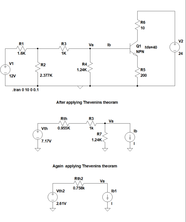
I can accurately calculate $I_b = \pu{2.09 mA}$ by using Kirchoff's voltage law, but I'm getting an inaccurate value ($I_b= \pu{213 \mu A}$) by applying Thévenin's theorem.
Is Thévenin's theorem being applied incorrectly for the circuit?
2 answers
Is the Thevenin's Theorem being applied incorrectly for the circuit ?
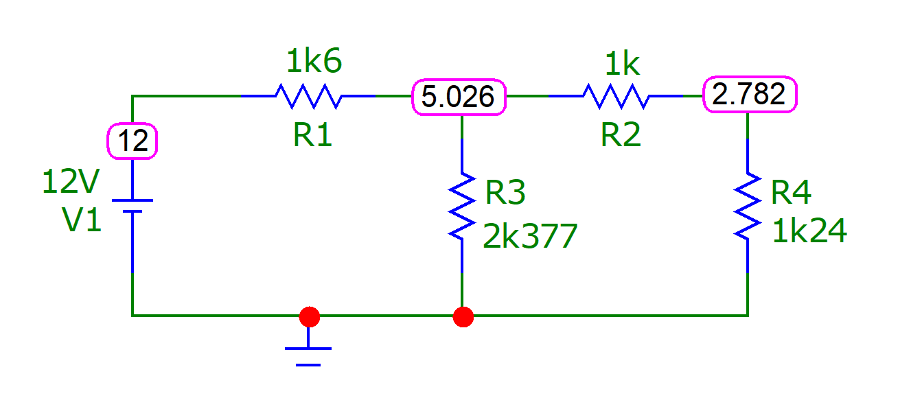
It's being applied inaccurately. The final Thevenin voltage should be 2.782 volts (rather than your calculated value of 2.61 volts). I calculate the Thevenin resistance to be 759 ohms (near enough to yours so that it doesn't matter). Double check with simulator for the Thevenin voltage: -
I can accurately calculate the Ib = 2.09mA by using Kirchoff's Voltage law
Then you have miscalculated because, if 2 mA were flowing into the base then, due to hFE (~40), the emitter current would be about 80 mA and, if 80 mA were flowing through the emitter resistor of 200 Ω then there would be an emitter voltage of 16 volts and clearly, that has to be nonsense.
1 comment thread
It seems like you did the reduction to a Thevenin source mostly right, although the final value is a bit off.
The original circuit we want to reduce to a Thevenin source is:
First we reduce V1, R1, and R2 to a Thevenin source. The resistance is R1//R2, and the voltage is the V1 voltage applied to the R1-R2 voltage divider. That yeilds:
R1 and R3 can be trivially combined:
The ultimate Thevenin resistance is now R1//R4, and the voltage is the new V1 applied to the R1-R4 divider:
Now we put this back into the original circuit:
R5 appears on the base times gain+1. (200 Ω)⋅41 = 8.2 kΩ. Let's say the B-E junction drops 700 mV. The base current is then:
IB = (2.78 V - 700 mV)/(759 Ω + 8.2 kΩ) = 232 µA
Note that reflecting the emitter resistance to the base by multiplying times gain+1 is only valid if there is enough collector voltage so that the stated gain is being realized. It should be obvious from inspection that the 10 Ω resistor is well low enough, but I'll do the calculation anyway to show what to do in cases it's not so obvious.
We determined that the base current is 232 µA. With a gain of 40, the collector current is therefore 9.3 mA. R6 therefore drops (9.3 mA)(10 Ω) = 93 mV. The drop across R5 is (200 Ω)(232 µA)⋅41 = 1.9 V, which is also the emitter voltage. The C-E voltage is therefore (24 V)-(93 mV)-(1.9 V) = 22 V. Silicon BJTs usually exhibit their stated gain after about 1 V C-E, so this is clearly plenty for the gain assumption to be valid.
NOTE: Calculating the currents with this accuracy is absurd for any case other than a homework assignment. In the real world, you generally only know the minimum gain the transistor is guaranteed to have. The upper limit is usually not specified, or is several times the minimum. I've personally measured transistors with 10x the minimum guaranteed gain. Circuits need to work over the whole range of valid gain a transistor might have. It's usually good to make sure the circuit works from the minimum gain to infinite gain.

0 comment threads