Technique to reset pulse transformer core quickly
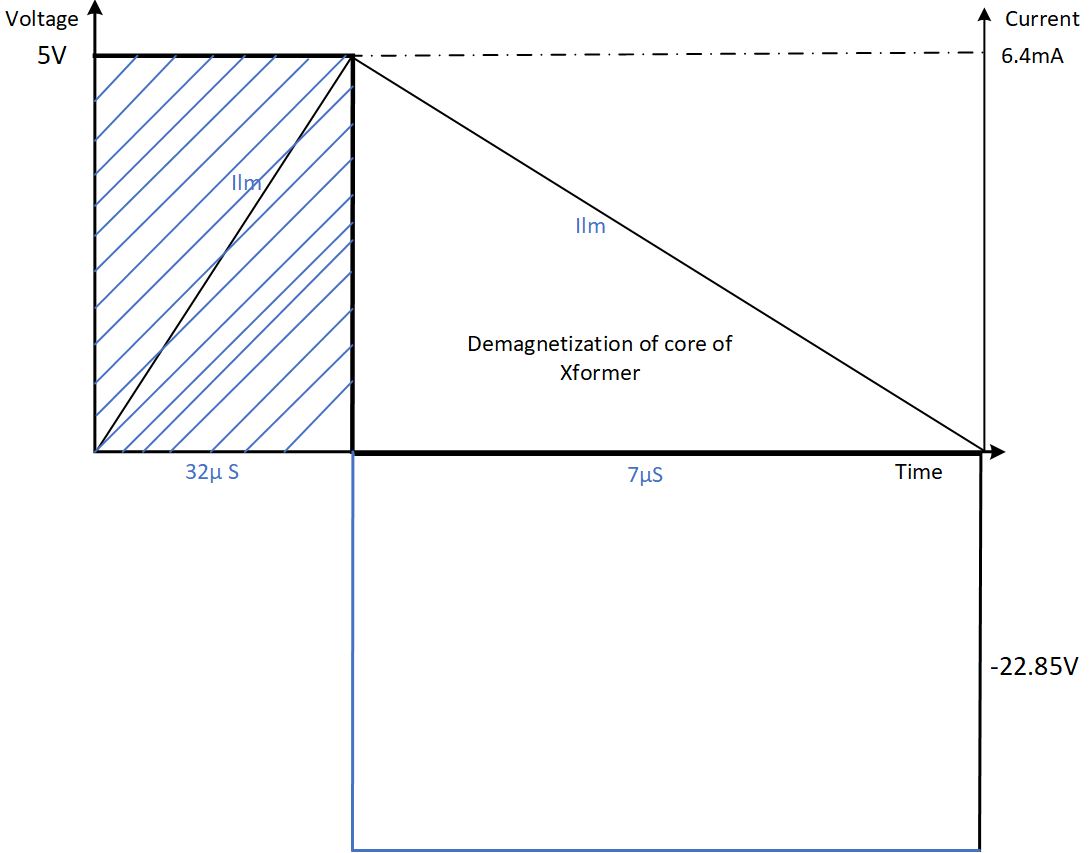
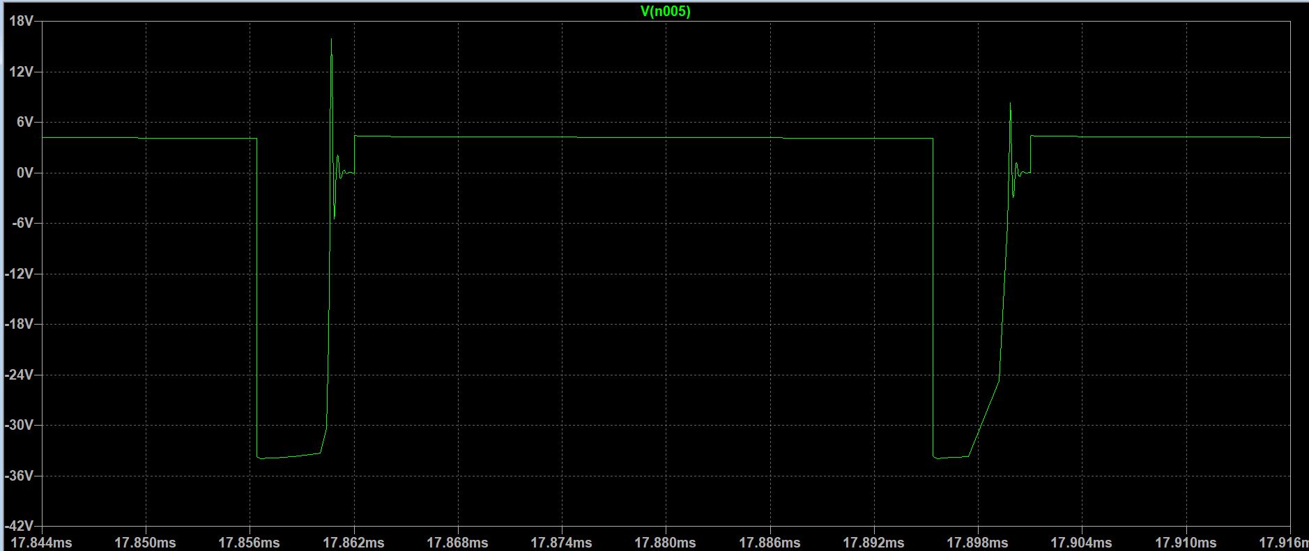
I am analysing a pulse transformer which is required to transfer below communication protocol pulse from primary to the secondary side. The pulse duration is 32 μs and off time available to reset the core is just 7 μs. Calculation shows that -22.85 V are required to reset the core within 7 μs.
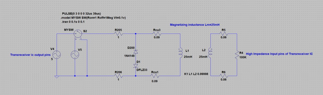
For simulation, I have used 33 V Zener and 1N4148 blocking diode.
Is there any way to reset a core quickly without having ground / reference terminal pulled towards negative voltage ? because when -22.85 V is applied across TTL logic pins like microcontroller,they will get damaged.
2 answers
Is there any way to reset a core quickly without having ground / reference terminal pulled towards negative voltage
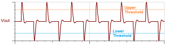
Unfortunately not but, if instead of trying to send the complete pulse through the transformer, you send edge information (i.e. use a series capacitor to perform a kind of differentiation), then you can adequately reconstruct the secondary voltage using a comparator with hysteresis. Here's what the output waveform would look like: -
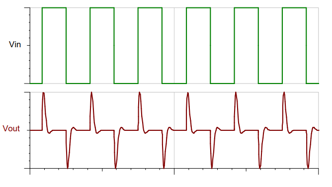
Below I've shown where you could set the upper and lower threshold limits for the comparator with hysteresis: -
Note that open-circuiting an inductor "resets" the magnetic field instantly. The downside is that this also generates infinite voltage for that infinitely small time.
Infinite voltage is obviously bad, but you should easily be able to tolerate "high enough" voltage relative to your 5 V drive. Use a separate transistor as a low side switch driving the low side of the primary, with the high side of the primary connected to the 5 V supply. That puts your desired 5 V across the primary when the switch is on.
When the switch is turned off, the magnetic field will collapse due to the current going to zero. The faster this happens, the higher the voltage the inductor will generate during the on to off transition. You have to manage this voltage to ensure it doesn't exceed the switch ratings. Basically, let the inductor make its own reverse voltage to "reset" the magnetic field. You design the circuit to tolerate a reasonably high voltage, while limiting it to what you know the components can handle.
One advantage you have is that current will be well known when the switch is turned off. With a resistor across the primary, you know that the kickback voltage won't exceed that current times the resistance. You can put a diode in series with the resistor so that extra current isn't required when the switch is on. This will result in a exponential decay of the current during the off time.
Here is the basic idea:
That transistor can withstand 80 V C-E. The resistor needs to be small enough to limit the kickback voltage so that the collector voltage doesn't exceed 80 V. Considering the 5 V supply voltage and 700 mV drop across the diode, the resistor voltage must be limited to 74.3 V. You know the inductor current at switch-off is 6.4 mA. The absolute maximum resistor value is therefore (74.3 V)/(6.4 mA) = 11.6 kΩ. 10 kΩ is a commonly available value that leaves some margin.
This circuit will cause the primary current to exponentially decay during the off time. The inductor-resistor time constant is L/R. From the charge-up time and resulting current, we can see that the inductance is 25 mH. The decay time constant is therefore (25 mH)/(10 kΩ) = 2.5 µs. Your off time of 7 µs allows for 2.8 time constants. That means the inductor current will decay to 6.1% of the original value during that time. If starting with 6.4 mA, the result will be 390 µA. That is unlikely to cause any trouble. The roughly fixed voltage across D1 during this time will actually cause the decay to be a little faster.
If you really want the current to go to zero before the next pulse, substitute the resistor for a Zener diode. Now you definitely need D1 since the Zener would otherwise short the collector to the 5 V supply during the on-time. As we calculated before, the Zener voltage can't exceed 74.3 V, and you need at least 23 V total for the current to reach 0 during the 7 µs off-time. That leaves plenty of room to find a suitable Zener diode. The 33 V Zener you already have would be fine, for example.
Note that the above numbers were driven by the use of the particular example transistor, which can withstand 80 V. A higher C-E rating allows for higher reverse voltage, which would result in faster decay of the inductor current.
Response to comments
The pin of the digital device creating the 0-5 V signal has little to do with this. It would be driving the base of the transistor in the circuit above. I didn't show the details of driving the transistor from a digital output since it's not that related to the question, and should be well understood before asking about the more advanced concept of driving the pulse transformer. If you don't have a good grasp of driving a transistor from a digital output, then ask about it separately.
The simplest base drive is a resistor in series between the digital output and the base. It can get fancier to reduce delays, particularly the on-to-off delay.
The kickback voltage can be reflected to the secondary, depending on what exactly it is connected to. Note that it would be in the opposite polarity from the "forward" pulse produced during the 32 µs on-time.

1 comment thread