Post History
I have recently finished designing a buck-boost converter for a job that uses a split (+/-) input power supply. Load power is taken equally from both positive and negative input supplies and, the ...
#11: Post edited
by
 Lorenzo Donati
·
2023-08-10T15:59:58Z (almost 2 years ago)
Lorenzo Donati
·
2023-08-10T15:59:58Z (almost 2 years ago)
Retagged.
#10: Post edited
by
 Andy aka
·
2022-10-16T15:11:27Z (over 2 years ago)
Andy aka
·
2022-10-16T15:11:27Z (over 2 years ago)
I have **recently finished** designing a buck-boost converter for a job that uses a split (+/-) input power supply. The load power is shared from both positive and negative input supplies and, the load is connected to 0 volts (mid-rail of the split input supply).- $$$$
- For a **single rail supply**, the standard approach would be this: -
- 
- I've not shown the MOSFET drive circuits because they're unimportant. So, my question is this: what design approach/topology would you choose when designing a buck-boost controller that operates from a split input power supply and drives a load connected to 0 volts.
- $$$$
- I'm looking for a basic circuit idea like the one above i.e. no need to show drivers etc..
- -----
- **Edited section**
- Olin came up with a solution using a transformer and thumbs-up for that but, I'm actually interested in a solution that doesn't use a transformer. I'm also interested in power levels of above 1 kW.
- - The input supply is +/-250 volts DC.
- - DC output is variable between 300 volts and 600 volts.
- My **recently finished** solution seemed novel because I couldn't find it when searching the internet. Hence, I'm interested if anyone else has a standard solution that matches what I came up with.
- Sorry for not making these things clear at the outset.
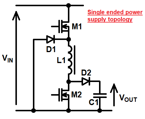
- I have **recently finished** designing a buck-boost converter for a job that uses a split (+/-) input power supply. Load power is taken equally from both positive and negative input supplies and, the load is connected to 0 volts (mid-rail of the split input supply).
- $$$$
- For a **single rail supply**, the standard approach would be this: -
- 
- I've not shown the MOSFET drive circuits because they're unimportant. So, my question is this: what design approach/topology would you choose when designing a buck-boost controller that operates from a split input power supply and drives a load connected to 0 volts.
- $$$$
- I'm looking for a basic circuit idea like the one above i.e. no need to show drivers etc..
- -----
- **Edited section**
- Olin came up with a solution using a transformer and thumbs-up for that but, I'm actually interested in a solution that doesn't use a transformer. I'm also interested in power levels of above 1 kW.
- - The input supply is +/-250 volts DC.
- - DC output is variable between 300 volts and 600 volts.
- My **recently finished** solution seemed novel because I couldn't find it when searching the internet. Hence, I'm interested if anyone else has a standard solution that matches what I came up with.
- Sorry for not making these things clear at the outset.
#9: Post edited
by
Andy aka
·
2022-10-16T14:16:15Z (over 2 years ago)
I have recently finished designing a buck-boost converter for a job that uses a split (+/-) input power supply. The load power must be shared from both positive and negative input supplies and, the load is connected to 0 volts (mid-rail of the split input supply).- $$$$
- For a **single rail supply**, the standard approach would be this: -
- 
- I've not shown the MOSFET drive circuits because they're unimportant. So, my question is this: what design approach/topology would you choose when designing a buck-boost controller that operates from a split input power supply and drives a load connected to 0 volts.
- $$$$
- I'm looking for a basic circuit idea like the one above i.e. no need to show drivers etc..
- -----
- **Edited section**
- Olin came up with a solution using a transformer and thumbs-up for that but, I'm actually interested in a solution that doesn't use a transformer. I'm also interested in power levels of above 1 kW.
- - The input supply is +/-250 volts DC.
- - DC output is variable between 300 volts and 600 volts.
- Sorry for not making these things clear at the outset.
- I have **recently finished** designing a buck-boost converter for a job that uses a split (+/-) input power supply. The load power is shared from both positive and negative input supplies and, the load is connected to 0 volts (mid-rail of the split input supply).
- $$$$
- For a **single rail supply**, the standard approach would be this: -
- 
- I've not shown the MOSFET drive circuits because they're unimportant. So, my question is this: what design approach/topology would you choose when designing a buck-boost controller that operates from a split input power supply and drives a load connected to 0 volts.
- $$$$
- I'm looking for a basic circuit idea like the one above i.e. no need to show drivers etc..
- -----
- **Edited section**
- Olin came up with a solution using a transformer and thumbs-up for that but, I'm actually interested in a solution that doesn't use a transformer. I'm also interested in power levels of above 1 kW.
- - The input supply is +/-250 volts DC.
- - DC output is variable between 300 volts and 600 volts.
- My **recently finished** solution seemed novel because I couldn't find it when searching the internet. Hence, I'm interested if anyone else has a standard solution that matches what I came up with.
- Sorry for not making these things clear at the outset.
#8: Post edited
by
Andy aka
·
2022-10-15T11:01:41Z (over 2 years ago)
- I have recently finished designing a buck-boost converter for a job that uses a split (+/-) input power supply. The load power must be shared from both positive and negative input supplies and, the load is connected to 0 volts (mid-rail of the split input supply).
- $$$$
- For a **single rail supply**, the standard approach would be this: -
- 
I've not shown the MOSFET drive circuits because they're unimportant. So, my question is this: what design approach would you choose when designing a buck-boost controller that operates from a split input power supply and drives a load connected to 0 volts.- $$$$
- I'm looking for a basic circuit idea like the one above i.e. no need to show drivers etc..
- -----
- **Edited section**
- Olin came up with a solution using a transformer and thumbs-up for that but, I'm actually interested in a solution that doesn't use a transformer. I'm also interested in power levels of above 1 kW.
- - The input supply is +/-250 volts DC.
- - DC output is variable between 300 volts and 600 volts.
- Sorry for not making these things clear at the outset.
- I have recently finished designing a buck-boost converter for a job that uses a split (+/-) input power supply. The load power must be shared from both positive and negative input supplies and, the load is connected to 0 volts (mid-rail of the split input supply).
- $$$$
- For a **single rail supply**, the standard approach would be this: -
- 
- I've not shown the MOSFET drive circuits because they're unimportant. So, my question is this: what design approach/topology would you choose when designing a buck-boost controller that operates from a split input power supply and drives a load connected to 0 volts.
- $$$$
- I'm looking for a basic circuit idea like the one above i.e. no need to show drivers etc..
- -----
- **Edited section**
- Olin came up with a solution using a transformer and thumbs-up for that but, I'm actually interested in a solution that doesn't use a transformer. I'm also interested in power levels of above 1 kW.
- - The input supply is +/-250 volts DC.
- - DC output is variable between 300 volts and 600 volts.
- Sorry for not making these things clear at the outset.
#7: Post edited
by
Andy aka
·
2022-10-15T11:01:00Z (over 2 years ago)
- I have recently finished designing a buck-boost converter for a job that uses a split (+/-) input power supply. The load power must be shared from both positive and negative input supplies and, the load is connected to 0 volts (mid-rail of the split input supply).
- $$$$
- For a **single rail supply**, the standard approach would be this: -
- I've not shown the MOSFET drive circuits because they're unimportant. So, my question is this: what design approach would you choose when designing a buck-boost controller that operates from a split input power supply and drives a load connected to 0 volts.
- $$$$
- I'm looking for a basic circuit idea like the one above i.e. no need to show drivers etc..
- -----
- **Edited section**
- Olin came up with a solution using a transformer and thumbs-up for that but, I'm actually interested in a solution that doesn't use a transformer. I'm also interested in power levels of above 1 kW.
- - The input supply is +/-250 volts DC.
- - DC output is variable between 300 volts and 600 volts.
- Sorry for not making these things clear at the outset.
- I have recently finished designing a buck-boost converter for a job that uses a split (+/-) input power supply. The load power must be shared from both positive and negative input supplies and, the load is connected to 0 volts (mid-rail of the split input supply).
- $$$$
- For a **single rail supply**, the standard approach would be this: -
- 
- I've not shown the MOSFET drive circuits because they're unimportant. So, my question is this: what design approach would you choose when designing a buck-boost controller that operates from a split input power supply and drives a load connected to 0 volts.
- $$$$
- I'm looking for a basic circuit idea like the one above i.e. no need to show drivers etc..
- -----
- **Edited section**
- Olin came up with a solution using a transformer and thumbs-up for that but, I'm actually interested in a solution that doesn't use a transformer. I'm also interested in power levels of above 1 kW.
- - The input supply is +/-250 volts DC.
- - DC output is variable between 300 volts and 600 volts.
- Sorry for not making these things clear at the outset.
#6: Post edited
by
Andy aka
·
2022-10-14T21:56:21Z (over 2 years ago)
- I have recently finished designing a buck-boost converter for a job that uses a split (+/-) input power supply. The load power must be shared from both positive and negative input supplies and, the load is connected to 0 volts (mid-rail of the split input supply).
- $$$$
- For a **single rail supply**, the standard approach would be this: -
- 
- I've not shown the MOSFET drive circuits because they're unimportant. So, my question is this: what design approach would you choose when designing a buck-boost controller that operates from a split input power supply and drives a load connected to 0 volts.
- $$$$
- I'm looking for a basic circuit idea like the one above i.e. no need to show drivers etc..
- -----
- **Edited section**
- Olin came up with a solution using a transformer and thumbs-up for that but, I'm actually interested in a solution that doesn't use a transformer. I'm also interested in power levels of above 1 kW.
- Sorry for not making these things clear at the outset.
- I have recently finished designing a buck-boost converter for a job that uses a split (+/-) input power supply. The load power must be shared from both positive and negative input supplies and, the load is connected to 0 volts (mid-rail of the split input supply).
- $$$$
- For a **single rail supply**, the standard approach would be this: -
- 
- I've not shown the MOSFET drive circuits because they're unimportant. So, my question is this: what design approach would you choose when designing a buck-boost controller that operates from a split input power supply and drives a load connected to 0 volts.
- $$$$
- I'm looking for a basic circuit idea like the one above i.e. no need to show drivers etc..
- -----
- **Edited section**
- Olin came up with a solution using a transformer and thumbs-up for that but, I'm actually interested in a solution that doesn't use a transformer. I'm also interested in power levels of above 1 kW.
- - The input supply is +/-250 volts DC.
- - DC output is variable between 300 volts and 600 volts.
- Sorry for not making these things clear at the outset.
#5: Post edited
by
Andy aka
·
2022-10-14T13:00:17Z (over 2 years ago)
- I have recently finished designing a buck-boost converter for a job that uses a split (+/-) input power supply. The load power must be shared from both positive and negative input supplies and, the load is connected to 0 volts (mid-rail of the split input supply).
- $$$$
- For a **single rail supply**, the standard approach would be this: -
- 
- I've not shown the MOSFET drive circuits because they're unimportant. So, my question is this: what design approach would you choose when designing a buck-boost controller that operates from a split input power supply and drives a load connected to 0 volts.
- $$$$
- I'm looking for a basic circuit idea like the one above i.e. no need to show drivers etc..
- -----
- **Edited section**
Olin came up with the obvious solution using a transformer and thumbs-up for that but, I'm actually interested in a solution that doesn't use a transformer. Sorry for not making that clear at the outset.
- I have recently finished designing a buck-boost converter for a job that uses a split (+/-) input power supply. The load power must be shared from both positive and negative input supplies and, the load is connected to 0 volts (mid-rail of the split input supply).
- $$$$
- For a **single rail supply**, the standard approach would be this: -
- 
- I've not shown the MOSFET drive circuits because they're unimportant. So, my question is this: what design approach would you choose when designing a buck-boost controller that operates from a split input power supply and drives a load connected to 0 volts.
- $$$$
- I'm looking for a basic circuit idea like the one above i.e. no need to show drivers etc..
- -----
- **Edited section**
- Olin came up with a solution using a transformer and thumbs-up for that but, I'm actually interested in a solution that doesn't use a transformer. I'm also interested in power levels of above 1 kW.
- Sorry for not making these things clear at the outset.
#4: Post edited
by
Andy aka
·
2022-10-14T12:58:50Z (over 2 years ago)
- I have recently finished designing a buck-boost converter for a job that uses a split (+/-) input power supply. The load power must be shared from both positive and negative input supplies and, the load is connected to 0 volts (mid-rail of the split input supply).
- $$$$
- For a **single rail supply**, the standard approach would be this: -
- 
- I've not shown the MOSFET drive circuits because they're unimportant. So, my question is this: what design approach would you choose when designing a buck-boost controller that operates from a split input power supply and drives a load connected to 0 volts.
- $$$$
I'm looking for a basic circuit idea like the one above i.e. no need to show drivers etc..
- I have recently finished designing a buck-boost converter for a job that uses a split (+/-) input power supply. The load power must be shared from both positive and negative input supplies and, the load is connected to 0 volts (mid-rail of the split input supply).
- $$$$
- For a **single rail supply**, the standard approach would be this: -
- 
- I've not shown the MOSFET drive circuits because they're unimportant. So, my question is this: what design approach would you choose when designing a buck-boost controller that operates from a split input power supply and drives a load connected to 0 volts.
- $$$$
- I'm looking for a basic circuit idea like the one above i.e. no need to show drivers etc..
- -----
- **Edited section**
- Olin came up with the obvious solution using a transformer and thumbs-up for that but, I'm actually interested in a solution that doesn't use a transformer. Sorry for not making that clear at the outset.
#3: Post edited
by
Andy aka
·
2022-10-14T10:41:29Z (over 2 years ago)
- I have recently finished designing a buck-boost converter for a job that uses a split (+/-) input power supply. The load power must be shared from both positive and negative input supplies and, the load is connected to 0 volts (mid-rail of the split input supply).
- $$$$
- For a **single rail supply**, the standard approach would be this: -
- 
- I've not shown the MOSFET drive circuits because they're unimportant. So, my question is this: what design approach would you choose when designing a buck-boost controller that operates from a split input power supply and drives a load connected to 0 volts.
- $$$$
I'm looking for a basic circuit like the one above i.e. no need to show drivers etc..
- I have recently finished designing a buck-boost converter for a job that uses a split (+/-) input power supply. The load power must be shared from both positive and negative input supplies and, the load is connected to 0 volts (mid-rail of the split input supply).
- $$$$
- For a **single rail supply**, the standard approach would be this: -
- 
- I've not shown the MOSFET drive circuits because they're unimportant. So, my question is this: what design approach would you choose when designing a buck-boost controller that operates from a split input power supply and drives a load connected to 0 volts.
- $$$$
- I'm looking for a basic circuit idea like the one above i.e. no need to show drivers etc..
#2: Post edited
by
Andy aka
·
2022-10-14T08:51:49Z (over 2 years ago)
- I have recently finished designing a buck-boost converter for a job that uses a split (+/-) input power supply. The load power must be shared from both positive and negative input supplies and, the load is connected to 0 volts (mid-rail of the split input supply).
- $$$$
- For a **single rail supply**, the standard approach would be this: -
- 
I've not shown the MOSFET drive circuits because they're unimportant. So, my question is this: what approach would you take when designing a buck-boost controller that operates from a split input power supply and drives a load connected to 0 volts.- $$$$
- I'm looking for a basic circuit like the one above i.e. no need to show drivers etc..
- I have recently finished designing a buck-boost converter for a job that uses a split (+/-) input power supply. The load power must be shared from both positive and negative input supplies and, the load is connected to 0 volts (mid-rail of the split input supply).
- $$$$
- For a **single rail supply**, the standard approach would be this: -
- 
- I've not shown the MOSFET drive circuits because they're unimportant. So, my question is this: what design approach would you choose when designing a buck-boost controller that operates from a split input power supply and drives a load connected to 0 volts.
- $$$$
- I'm looking for a basic circuit like the one above i.e. no need to show drivers etc..
#1: Initial revision
by
Andy aka
·
2022-10-14T08:46:29Z (over 2 years ago)
Buck-boost converter fed from split input supply
I have recently finished designing a buck-boost converter for a job that uses a split (+/-) input power supply. The load power must be shared from both positive and negative input supplies and, the load is connected to 0 volts (mid-rail of the split input supply). $$$$ For a **single rail supply**, the standard approach would be this: -  I've not shown the MOSFET drive circuits because they're unimportant. So, my question is this: what approach would you take when designing a buck-boost controller that operates from a split input power supply and drives a load connected to 0 volts. $$$$ I'm looking for a basic circuit like the one above i.e. no need to show drivers etc..