Buck-boost converter fed from split input supply
I have recently finished designing a buck-boost converter for a job that uses a split (+/-) input power supply. Load power is taken equally from both positive and negative input supplies and, the load is connected to 0 volts (mid-rail of the split input supply).
For a single rail supply, the standard approach would be this: -
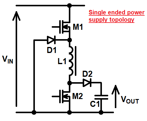
I've not shown the MOSFET drive circuits because they're unimportant. So, my question is this: what design approach/topology would you choose when designing a buck-boost controller that operates from a split input power supply and drives a load connected to 0 volts.
I'm looking for a basic circuit idea like the one above i.e. no need to show drivers etc..
Edited section
Olin came up with a solution using a transformer and thumbs-up for that but, I'm actually interested in a solution that doesn't use a transformer. I'm also interested in power levels of above 1 kW.
- The input supply is +/-250 volts DC.
- DC output is variable between 300 volts and 600 volts.
My recently finished solution seemed novel because I couldn't find it when searching the internet. Hence, I'm interested if anyone else has a standard solution that matches what I came up with.
Sorry for not making these things clear at the outset.
1 answer
One possibility is to use a transformer. The power input can then come from across the plus and minus input power. The output can be referenced to whatever you like, which in this case would be ground. The output current would always return to ground, so not effect the current balance between the plus and minus input supplies. Here is the basic topology for a flyback converter:
It does seem a bit clunky to use a transformer when isolation isn't really needed, but it does completely solve the problem of input supply imbalance. The switching topology is also simplified because you don't need buck-boost. Overall, maybe it's not so bad.

3 comment threads