How Relay inrush current limiter works?
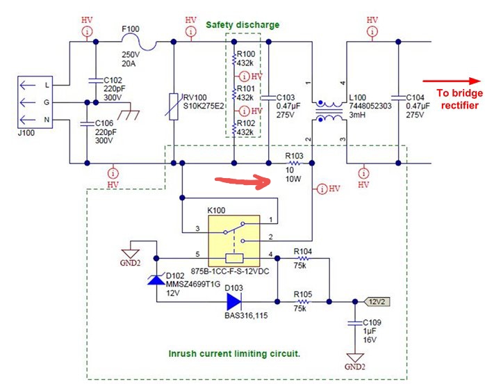
In this circuit below the relay circuit part is acting as an inrush current limiter, but I can't understand how it works since the current is flowing in both conditions where the relay is open or closed!
Edit: so it's all about the switching time, relays are known for slow switching time which is supposed to be a negative criteria, I checked the Datasheet of the relay and its 9~10 Ms.
1 answer
It's a current limiter, not eliminator. The current is always supposed to flow, but be limited at startup to avoid high inrush current.
All the relay does is short out R103 when activated. The relay starts out off, so R103 is in series with the input power when the device is first plugged in or turned on. The 10 Ω of R103 keeps the current limited. It's not meant to allow the device to fully function, but enough to allow the input capacitors of the power supply, or whatever else might take a large initial slug of current, to get past that point.
Eventually the 12 V supply comes up, which then turns on the relay. That shorts out R103, and the device can draw its full normal operating current without its input voltage sagging. There may be a small current spike right when the relay closes, but presumably that has been calculated to be within tolerable limits.
The device may have additional circuitry inside that doesn't run the main device function until after the relay has been on for a few 100 ms or so. By that time, the internal DC supplies should be up to their intended voltages.

0 comment threads