Testing instrumentation amplifier with differential signal
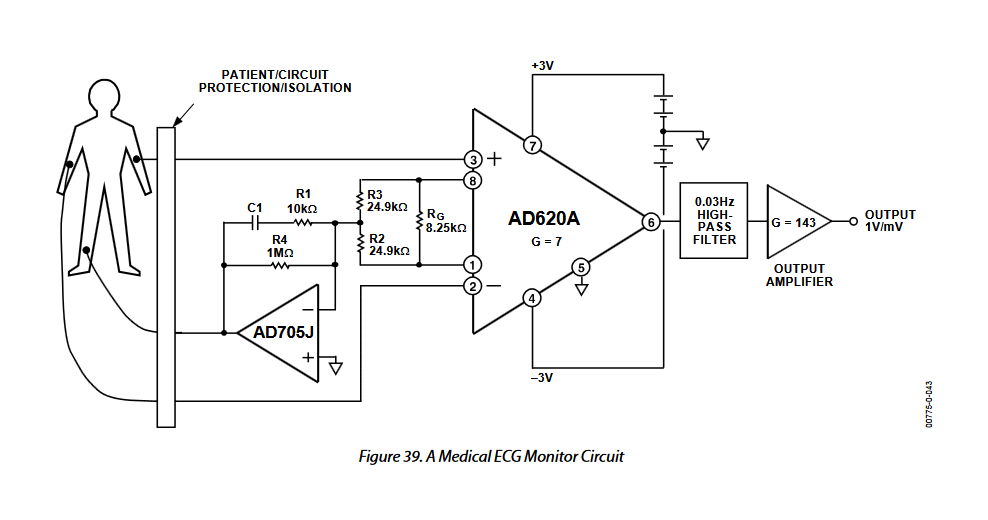
I am using the AD620 as instrumentation amplifier to amplify the body's ECG signal. An ECG is a differential signal (measured with two electrodes) and I want a differential gain of Gd=1000 .
The datasheet has this formula: $G_d=1+\frac{49.4 \: \text{k}Ω}{R_G}$ , so using two resistors of 27 Ω gives me a gain of 916 which is good enough.
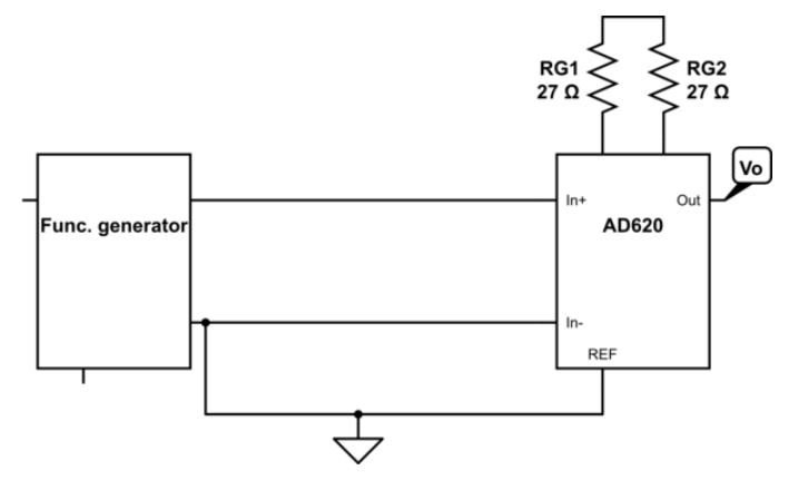
I want to test the amplifier, by generating a 5 mV peak-peak sinusoid, send it into the in-amp and expect around 5 V peak-peak on the output. So I thought of using this setup: -
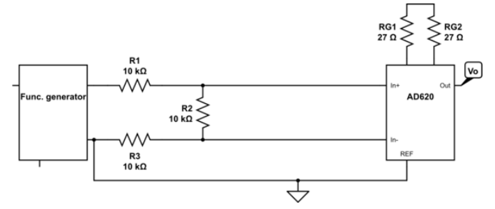
My instructor suggests generating a 15 mV peak-peak sinusoid and using this setup instead: -
Question: Why is the second setup needed to test my differential amplifier? What does the second setup do that the first one doesn't?
3 answers
You are accessing this answer with a direct link, so it's being shown above all other answers regardless of its score. You can return to the normal view.
One of the reasons to follow the advice of your instructor is that page 17 of the datasheet identifies the need for ground return paths for input bias currents. Your initial setup may or may not work depending on the specific function generator and its output settings, because there is no current flow into the AD620 In+ pin. The setup proposed by your instructor allows the current to flow from the function generator through R1>R2>R3>ground.
0 comment threads
It is important to realize that an ECG signal is high impedance and this easily picks up line voltage E-fields. Using a 50 Ohm sig.gen. is a poor simulation of the use of this circuit and also negates any common mode rejection using it as a single-ended amplifier with one input grounded. Ground by definition means zero volts as a reference, but adding a wire which acts as an inductive antenna to the ground means you will not have 0.000 mV anymore.
Thus the advice to simulate electrode resistance with 100k is rational. To achieve the best CMRR all paths must be balancing such as the two Rgs' the wires or else shielding them or back-driving the common-mode voltage from the middle of the two Rg's becomes your null point which when buffered and attached to the body suppresses the common mode stray line noise with negative feedback. The R2 is optional in this case but is useful when it is not connected to the sig.gen.
1 comment thread
I think the biggest reason is that it may be difficult to control your function generator with an output of only 5 mV. Some function generators have different output ranges that are switched, then a volume knob that lets you select from 0 to the maximum for the current range. Even if it has a 100 mV range, you are still only asking for 5% of that. It may be difficult to adjust the volume pot with any precision at that level.
I would attenuate even more than just by 3. Make it so that the function generator puts out between 50% and 75% of its range. That should allow for comfortable setting precision, without pot scratchiness getting in the way.
One drawback of your instructor's method is that the common mode signal will be even higher relative to the differential signal you are trying to measure. For a differential amplifier, you want to test common mode and differential mode signals separately. Seeing the result of just one composite signal doesn't tell you everything is working. At least do one test with both inputs tied together and driven relative to ground. Ideally you get no signal out. You want to make sure the resulting signal is attenuated by the minimum common mode rejection the setup should provide.
0 comment threads

0 comment threads