How is it possible to perform a open circuit test on a induction motor?
During the open circuit test of a induction motor ,not any current flows inside the rotor.But how can we achieve such a thing?
Here is the ping configuration of a induction motor:
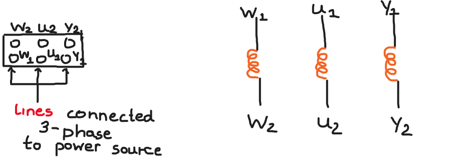
The coils of the stator/rotor will be always connected to the power source and depending on how we connect the pins labelled $W_{2}$,$U_{2}$,$Y_{2}$ together we end up with a Wye or Delta configuration.So if the coils of stator/rotor are always connected to the power source how can we create the circumstances for a open circuit test?
3 answers
You are accessing this answer with a direct link, so it's being shown above all other answers regardless of its score. You can return to the normal view.
~ In an open circuit test, also known as a no-load test, an induction motor is operated without any mechanical load connected to its shaft. The purpose of this test is to determine the no-load losses, core losses, and magnetizing current of the motor.
~ General Purpose: efficiency and performance of the motor under operating conditions.
~ Here's how the open circuit test on an induction motor is typically conducted:
Setup: Connect the stator winding of the motor to a suitable power supply. The stator winding is typically connected in either a delta (Δ) or a star (Y) configuration, depending on the motor's design. Ensure that the motor is properly grounded for safety.
Measurement Instruments: Connect suitable measuring instruments to the motor for measuring parameters such as voltage, current, and power. These instruments may include voltmeters, ammeters, wattmeters, and power analyzers.
No Load: Make sure there is no mechanical load connected to the motor shaft. The motor runs freely without any external load during the test.
Voltage and Frequency: Apply rated voltage and frequency to the motor. The rated voltage is the voltage at which the motor is designed to operate.
Measurements: Measure and record the following parameters:
- Line voltage (V)
- Line current (I)
- Active power (P)
- Reactive power (Q)
- Apparent power (S)
- Power factor (PF)
Calculations: Calculate the following values:
- Total power (P + jQ) = S
- Power factor (PF) = P / S
- Magnetizing current = I * √(1 - PF^2)
- Core losses (Pc) = P - Piron
- (Piron is the stray power loss in the iron core)
Analysis: The active power measured during the test represents the core losses, friction losses, and windage losses of the motor when it is running without any load. The magnetizing current reflects the current required to establish the magnetic field in the motor's stator and rotor. This current contributes to the overall power factor of the motor.
The open circuit test helps determine the losses that occur in the motor's core, enabling the calculation of its efficiency. It provides valuable information for motor performance analysis and helps in selecting the appropriate motor for a given application.
ESL Tip:
AN Induction motor starts with a vowel so the word before is AN to make it sound better than A.
To truly "open circuit test" a motor as I interpret it, remove it from power, and measure the following:
-
Using an Ohmmeter, measure each winding resistance. Start from W1 to W2. This will be some value, such as 5.1Ω.
-
Measure U1 to U2 and it should be very close to the previous value; within 10% or better.
-
Measure Y1 to Y2 and likewise. If any one is greater than 10% different than the others, then that winding is damaged and running the motor could be dangerous.
-
Still using the Ohmmeter, measure "across" various windings, such as W1 to U2 and vice-versa. All should measure "open" or infinite resistance (no winding there.) My suspicion is that there are other connections not evident (motor might already be wired for star or delta configuration), and this will find those connections. Draw these on paper to figure out how it is really wired.
-
Using an Ohmmeter which can read very high Ohms (giga-Ohmmeter or "insulation tester" would be best), check the resistance between all windings and motor chassis Earth ground. Anything seen should be 20MΩ or higher, indicating that there is almost zero electrical flow between these "hot" windings and the chassis. If one reads substantially lower than the other (say 10MΩ), then that indicates the winding insulation is degraded and may soon catastrophically fail. Anything under 5MΩ is bad and should not be run.
-
Most consumer single-phase motors only have a thermal cut-out switch. But three-phase motors usually have either an overall thermal switch or a (simple to complex) temperature sensor. Find a datasheet for the motor model and check the thermal sensor. It may be normally closed, open, or some resistance value depending on temperature. If that isn't working correctly, it will prevent the motor from running in the field application.
-
If the motor has any feedback devices (generator/tach, hall sensors, resolver, encoder, etc.), try to test that according to the motor datasheet/feedback device manual. Just try to ensure they work. A misbehaving or mis-wired feedback device can cause the motor to run erratically in the field, run backwards, accelerate instantly, etc.
If all of these "static tests" pass, then the motor is good to be run-tested, which others have described here.
P.S. Could the motor terminals be labeled U,V, and W? There are many possibilities, but most frequently these three letters are used for motors today.
0 comment threads
Your basic problem is that the motor needs some applied power to generate any EMF, but if you apply that power then its not an open circuit test.
For a true induction motor you're probably stuck. You'll have to measure various parameters separately while the motor is being driven. By measuring the voltage, current, and phase of each winding you can eventually deduce the same parameters that could have been measured more directly with an open circuit test.
For completeness, it is possible to sortof measure the open circuit voltage of a motor while being driven with three stator windings as you show, but that has permanent magnets on the rotor instead of relying on induction to create the rotor's magnetic field. Use a drive scheme where each winding goes thru the sequence of positive, open, negative, open, etc. There are 12 distinct drive phases in one magnetic rotation. You can measure the generated EMF during the open phases.
One issue is that the open phase of each winding is during its EMF zero crossing. Still, that doesn't mean zero the whole time. Sensorless drive schemes rely on measuring the timing of the zero crossing.
Another means is to get the motor spinning fast, then watch all the open circuit voltages as it coasts to a stop.
0 comment threads

1 comment thread