Ceramic capacitor "memory" effect?
I have run into an interesting phenomenon related to ceramic capacitors. This question is part of the effort to understand the issue, and eventually work around it. But first, some background of this particular situation is required.
Device background
I have designed a high-accuracy 32-channel ohmmeter. It is intended for an industrial application to measure the outputs of sensors that present a variable resistance in response to what they are measuring.
The things being measured change relatively slowly, like temperature and liquid levels in tanks. Several seconds of response time to settle within the noise floor is acceptable.
Accuracy is important, more than your typical ohmmeter. Ideally we'd like to be off by no more than 1 Ω over the working range of about 100 Ω to 40 kΩ. That's 25 PPM at the high end, or over 15 bits.
Here is a simplified schematic of one resistance input channel:
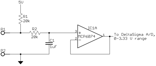
R1 is a low-drift resistor. The voltage reference for the A/D is 2/3 of the 5V line created with a voltage divider. The measurement is therefore ratiometric, and the absolute value of the 5 V line is not critical.
The buffered signal from the opamp directly drives the input of a delta-sigma A/D run continuously at roughly 60 Hz rate. R2 and C1 are intended to eliminate high frequencies (like radio station pickups) that are out of range for the opamp, and to attenuate frequencies above 30 Hz to prevent aliasing artifacts. More filtering is done in firmware, but that's not the point here.
The three main sources of error are the absolute value of R1, any offset voltage caused by the opamp or inherent in the A/D input, and the actual divide ratio from the 5 V line to the A/D reference. The strategy is measure each channel in production, save calibration constants, and have the firmware apply calibration correction each A/D reading.
Everything I've described so far is working quite well, exactly as intended.
Calibration
To calibrate each channel, measurements are taken with three highly accurate resistors connected to the input. These are chosen to result in A/D readings near middle and ends of its range. The results go into software that computes the actual values of R1, offset voltage, and A/D reference divide ratio. These are then used to create constants used by the firmware to correct each A/D reading.
Again, all this is working very nicely, exactly as intended.
Settling time
The software that gets the readings resulting from the reference resistances has to make sure the readings are fully settled. To do this, it gets sequences of 64 readings averaged together from the firmware, applies a little low-pass filtering, and waits for the result to reverse its direction of drift. That means that the values have settled to where the random noise makes them go up and down. 256 new readings are then averaged to be the official settled A/D value for the particular reference resistance.
The time constant of the filter caused by C1 should be 20 to 33 ms over the range of 0 to 40 kΩ being measured. Even at 33 ms, the signal should settle to one part in 1 M by 470 ms (14 time constants). In other words, settling to a new value shouldn't take more than half a second.
The software that looks for the filtered value going up and down (as opposed to converging in a single direction) does apply some low-pass filtering. This was necessary to prevent declaring the readings settled too soon. Without filtering, the blocks of 64 averaged readings could still be seen to drift in one direction overall, even if individual averages were bouncing up and down a little.
The software applies three poles of LPF with a filter fraction of 0.6 each pole. That settles to one part in 1 M in 21 seconds, which is well below the noise floor.
What the ... ?
I was expecting 10 to 20 seconds to get fully settled readings. It seems to take a bit more than that for high resistances (high end of A/D range). Something isn't quite right here, but it's not way off.
However, the really perplexing part is that it takes about a minute for low resistances like 100 Ω to settle according to the method described above. Nothing in the system should react anywhere near that slowly.
Capacitor makes a difference
After looking into thermal effects and not finding anything, I started wondering about the capacitor. Is it possible that a non-ideal characteristic of the capacitor causes some charges to get "stuck" at low voltages that then drain out slowly?
The original capacitors were generic ceramic 0805 surface mount. I didn't specify anything special because the low-pass filter rolloff frequency caused by C1 isn't critical. I didn't think the capacitor details mattered much as long as the leakage was low. Any ceramic seemed like it would do.
However, swapping in different capacitors changes things, even with all being 1 µF. I found an old 1 µF cap of unknown dielectric that is maybe 15 x 10 x 4 mm in a glazed ceramic package. With it, 100 Ω settles in about 30 seconds, or about twice as fast as the original. Other capacitors resulted in different values.
Finally, the question
What is going on here? Do some dielectrics release the last few PPM of charges more slowly? If so, what dielectrics do and don't? What kind of capacitor should I use?
I tried searches like "ceramic capacitor memory effect", but didn't find anything.
2 answers
Preface
English isn't my first language.
I'm still pretty green relatively as an electrical engineer with 3 years out of B.S. program and in the medical industry.
This is my first post on any stack exchange type of forums. Apologies for any forum taboo or mistakes they were not intentional.
Possible Answer
Olin I think you're right about the "ceramic capacitor memory effect". The google search you probably missed is for dielectric absorption which is similar to magnetic remanence.
A quick read of the wiki (in my opinion) seems to give insight into what you're experiencing.
the settling time might take longer to settle because even if the capacitor is discharged fully the cap self charges back to up to some % of the original voltage which is based on dialectic (see Measurement section of linked wiki article above).
That self charging is likely confusing the software because it still thinks the capacitor voltage is still stabilizing before it reaches some type of equilibrium.
you can probably run a test on the caps you've tried so far to see how long it takes them to settle to an equilibrium condition as seen by the software.
or
You might be able to add a hard time stop to settling in your software when measuring certain resistance ranges. The hard time stop to "finish" settling would likely need some heuristic tuning. But you already know generally speaking how long it should take based on your 14 time constants figure.
I hope this helps. Happy holidays.
0 comment threads
I have never seen this slow drift in ceramic caps, yet I have seen fast memory effect drift in S&H designs using high Dk ceramic capacitors in the 70's. So I have learnt that all ceramic caps have memory effects (except low Dk C0G/NP0's). The capacitance also changes with DC voltage, so Ic= VdC/dt + CdV/dt has a longer time constant as the voltage decays with R. I think of it as a partial response of an electric double layer effect. Although it is not as noticeable as the memory effect of all electrolytics, both capacitors and batteries. I am not referring to the nostalgia of NiCad batteries that need a full discharge to remember their full capacity, but the memory effect of the previous voltage after an impulse short circuit and how they slowly return from a much large RC time constant.
Capacitors that seem to have no memory effect are low Dk like all the plastic types. PTFE, Polyester, Polyurethane, etc.
I don't see the need for R2 to match R1 so C1 could be much smaller with a larger R2.
All the rest of your design sounds excellent.
0 comment threads


5 comment threads