CAN BUS monitoring with a LED
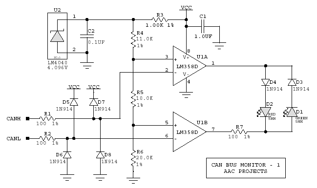
Hi, how can I use can bus monitoring through a simple led without disturbing the can line , I started with a diagram found on this forum, I need your help to correct where necessary, I want to use it as an external source (12-14v) Thanks !
3 answers
I've done similar things on UART lines, but for significantly lower baudrates (9600 etc) than traditionally used on most CAN buses.
It's also easier to do when you have 5V guaranteed to be well-over the LED Vfwd, which the CAN lines do not necessarily live up to. For instance there are 3.3V supplied CAN transceivers designed to be within spec and yet just deliver +3.3V rather than the 2.5+1=3.5V on CANH. Also, if someone messes up the installation and mixes CANH and CANL, you may end up with a situation where one line dips and the other goes higher than expected.
At most baudrates and payloads, a CAN frame is too fast to cause anything but flickering at best. Notably the human eye is unlikely to tell the difference between flicker caused by repeated error frames or valid packages, so there is a chance that the LED will not even tell you if the communication is working or broken. You'd be creating some manner of crude bus load indicator. Not very useful or reliable - so I'm sensing an "XY question" - what is your actual goal with this?
As mentioned in other answers, a MCU pin flipping a LED or a one-shot timer IC (monostable multivibrator) would be better solutions, the MCU pin one being the cheapest and most flexible - it could PWM drive the LED for example if current comsumption matters.
0 comment threads
You'll need a differential comparator, something like what was suggested in here.
1 comment thread
CAN lines in the most common implementation have 60 Ω impedance between them. Anything that is substantially larger than that won't effect the lines much. I'd use 1 kΩ at least, preferably more. The lead from the bus line to the resistor must also be short to minimize the characteristic impedance disruption of the bus.
That all said, putting an indicator directly on a CAN line is not a good idea in the first place. Think of what the user really wants to know in the field, which is whether CAN messages are being transmitted and received. This is best done by the microcontroller when it transmits and receives packets. Now there is no electrical impact on the CAN bus at all.
Another advantage of having the micro control the CAN activity LEDs is that it can do pulse stretching. One CAN frame is usually too short to cause a reliably visible blip on an LED. I found that 20 ms is about right for the minimum LED blip duration. The firmware essentially implements a retriggerable one-shot for each event you want to show activity for.
1 comment thread

1 comment thread