2 answers
Is there a scientific way to estimate the resistance of a pogo pin?
Ultimately there must be, but it generally requires knowing things you don't know.
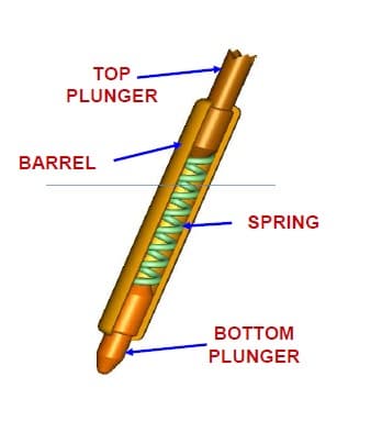
Worrying about the resistance of the barrel and spring is missing the point. The limiting factor will be the small contact area between the circuit board and the pogo pin point.
In any case, this is something you look up in the datasheet. The pogo pin manufacturer should be able to tell you what the maximum guaranteed resistance is between the pin and whatever it is touching, for different points and surfaces.
I agree with Olin that unknown contact area is the biggest variable.
I think the scientific way is to test and verify each contact using a 4 pin kelvin bridge.
The sum of 2 pins carrying constant current can be measured as voltage by 2 adjacent pins on pads sufficiently large.
It probably would be more than a double digit mohm range and not useful for measurements in this range due to the variation in contact force and pin vs crown style,and solder penetration with resulting contact area being a large variable.
I recall when I had to prove to UL that my method of grounding a powder-coat electro-painted chassis did not require masking an area for a PE ground lug to be fastened. Instead, I used a welded stud where the threads were capped and I predicted and verified that the contact area of 3 thread turns would be so far below the UL 100 mohm spec for a PE ground connection that it was approved by UL for my design in a VOIP PoE box I designed for Avaya(nee Lucent). This enabled my sheet metal supplier to cut more costs in the painting fabrication of the 1U rack box. I supplied UL with the Kelvin resistance test results, and they verified and approved the design deviation.
Pogo Pins are all AU plated and much lower resistance in the barrel. But the wire-wrap length was too inductive (10nH/cm). The pin length and solder penetration area has been OK for RF measurements for me (<100MHz) with 50 ohm coax directly to the pins but I would not trust it to measure milliohm trace resistance results unless a Kelvin bridge method was used.
Is there another reason why you need to know beside wearout?
0 comment threads


0 comment threads